Lithium rechargeable battery
a rechargeable battery and lithium technology, applied in the direction of cell components, sustainable manufacturing/processing, wound/folded electrode electrodes, etc., can solve the problem of limit in providing a rechargeable battery having low internal resistance, and achieve the effect of reducing internal resistance, improving charge/discharge efficiency, and facilitating rapid charge/discharg
- Summary
- Abstract
- Description
- Claims
- Application Information
AI Technical Summary
Benefits of technology
Problems solved by technology
Method used
Image
Examples
first embodiment
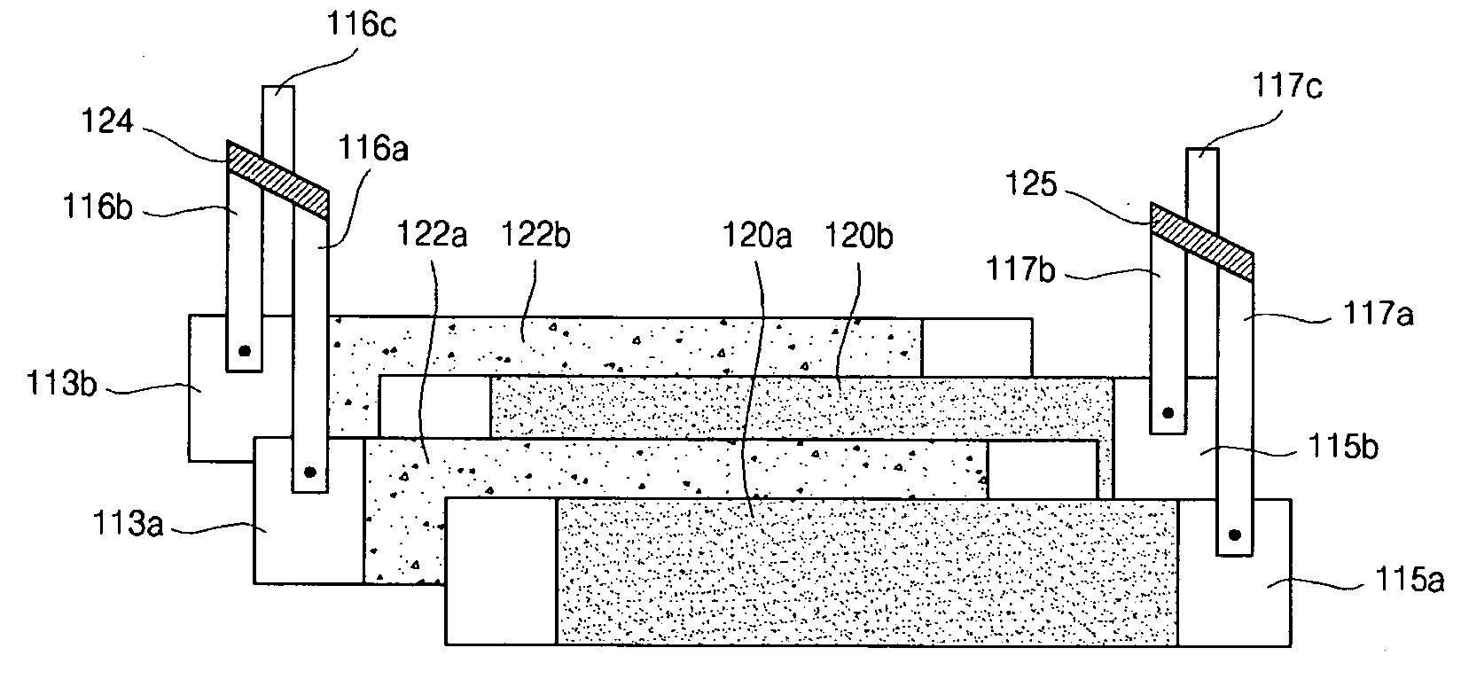
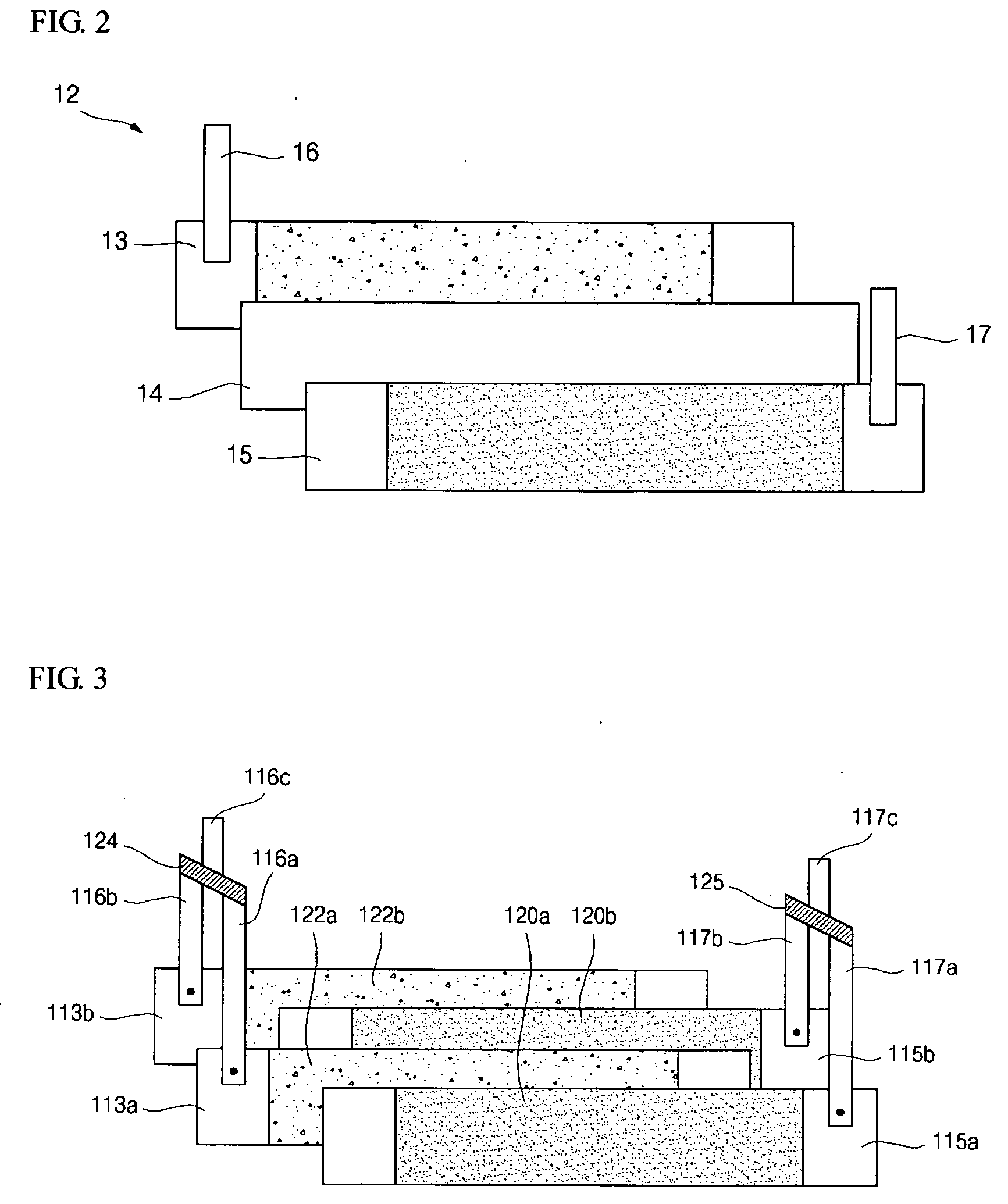
[0030] Referring to FIG. 3, the electrode assembly according to the present invention may be formed by winding two first electrode plates 113a and 113b two second electrode plates 115a and 115b, with a separator (not shown) interposed between first electrode plate 113a and second electrode plate 115a, and another separator (not shown) interposed between first electrode plate 113b and second electrode plate 115b, into a jelly roll.
[0031] The electrode assembly may include one or more additional layers of electrode plates where an additional layer includes an additional first electrode plate, an additional second electrode plate, and an additional separator interposed between the first electrode plate and second electrode plate. Further, an additional first electrode plate is fabricated and installed as described for the first electrode plates 113a and 113b, and a second electrode plate is fabricated and installed as described for second electrode plates 115a and 115b.
[0032] The sepa...
second embodiment
[0050] As shown in FIG. 4, one electrode tab 216a of the first electrode tabs 216a and 216b may be bent and coupled to the other first electrode tab 216b without using a separate conductive interconnection interposed between the two first electrode tabs. Then, the first electrode tab 216b can be extended sufficiently to electrically couple with a terminal. Additionally, one electrode tab 217a of the second electrode tabs 217a and 217b may be bent and coupled to the other second electrode tab 217b without using a separate conductive interconnection interposed between the two second electrode tabs. Then, the second electrode tab 217b can be extended to electrically couple with a terminal. as shown in FIG. 4, there is no need for a separate conductive interconnection nor a separate electrode tab for coupling the electrode tabs with a terminal, thus simplifying the manufacturing process for the electrode assembly.
[0051]FIG. 5 shows an exploded perspective view of a third exemplary embo...
third embodiment
[0053]FIG. 6 shows an exploded perspective view of a lithium rechargeable battery incorporating the electrode assembly according to the present invention.
[0054] A lithium rechargeable battery according to the present invention comprises a can 410, an electrode assembly 412 contained in the can 410, and a cap assembly 420 that is coupled to the top of the can 410.
[0055] The can 410 can be made in an approximately rectangular shape with an open top, and of a metal that is light and soft, such as aluminum, aluminum alloy, or stainless steel. The can 410 may function as a terminal.
[0056] The electrode assembly 412 includes first electrode plates 413a and 413b, second electrode plates 415a and 415b, and separators 414a and 414b. The first electrode plates 413a and 413b and the second electrode plates 415a and 415b may be layered alternately with the separators 414a and 414b interposed between both electrode plates and then may be wound into a jelly roll. First electrode tabs 416a and 4...
PUM
 Abstract
Description
Claims
Application Information
 - R&D
- Intellectual Property
- Life Sciences
- Materials
- Tech Scout
- Unparalleled Data Quality
- Higher Quality Content
- 60% Fewer Hallucinations
Browse by: Latest US Patents, China's latest patents, Technical Efficacy Thesaurus, Application Domain, Technology Topic, Popular Technical Reports.
© 2025 PatSnap. All rights reserved.Legal|Privacy policy|Modern Slavery Act Transparency Statement|Sitemap|About US| Contact US: help@patsnap.com


