
Flexible circuit board, electronic circuit device, and mobile communication terminal

a flexible circuit board and electronic circuit technology, applied in the direction of laminating printed circuit boards, electrical apparatus construction details, semiconductor/solid-state device details, etc., can solve the problems of excessive deformation of the electronic circuit mounting portion, deformation of the connector terminal, and extremely small space for receiving mounted components, etc., to achieve the effect of convenient mounting

Inactive Publication Date: 2006-06-15
NEC CORP
View PDF20 Cites 63 Cited by
  • Summary
  • Abstract
  • Description
  • Claims
  • Application Information

AI Technical Summary

Benefits of technology

[0015] The present invention has been made in view of the above, and therefore has an exemplary feature to provide a flexible circuit board that can be easily mounted on a frame of an electronic circuit device without generating of torsion, peeling, and the like in electronic circuit mounting portions and a connector mounting portion irrespective of mounting order of the electronic circuit mounting portions and the connector mounting portion on the electronic circuit device.
[0018] With the above structure, the flexible circuit board of the present invention can be easily mounted on the frame without generating of torsion, peeling, and the like in the electronic circuit mounting portions and the connector mounting portion irrespective of the mounting order of the electronic circuit mounting portions and the connector mounting portion on the electronic circuit device.

Problems solved by technology

Therefore, a space for receiving mounted components is becoming extremely small.
This may lead to deformation of a connector terminal.
This force causes excessive deformation of the electronic circuit mounting portion.
As a result, the mounted components may be peeled off or damaged.
Furthermore, JP 06-048321 U does not disclose that a plurality of circuit boards is arranged in different directions to be mounted on an electronic circuit device.

Method used


Image

  • Flexible circuit board, electronic circuit device, and mobile communication terminal
  • Flexible circuit board, electronic circuit device, and mobile communication terminal
  • Flexible circuit board, electronic circuit device, and mobile communication terminal

Examples


Embodiment Construction

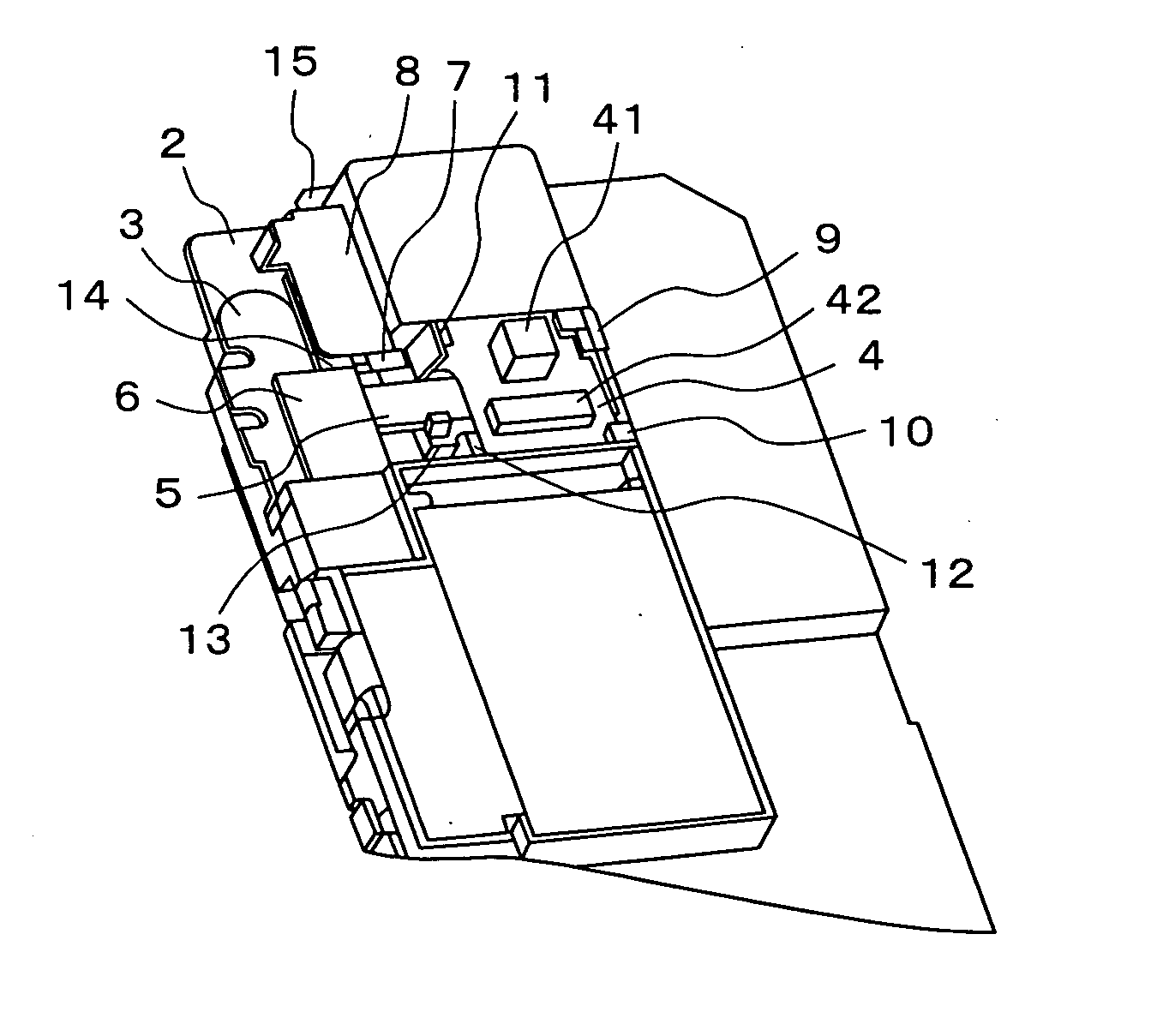
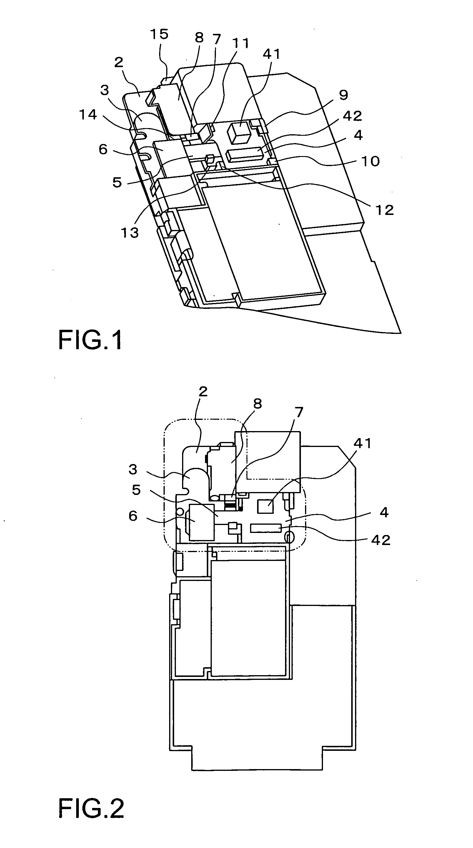
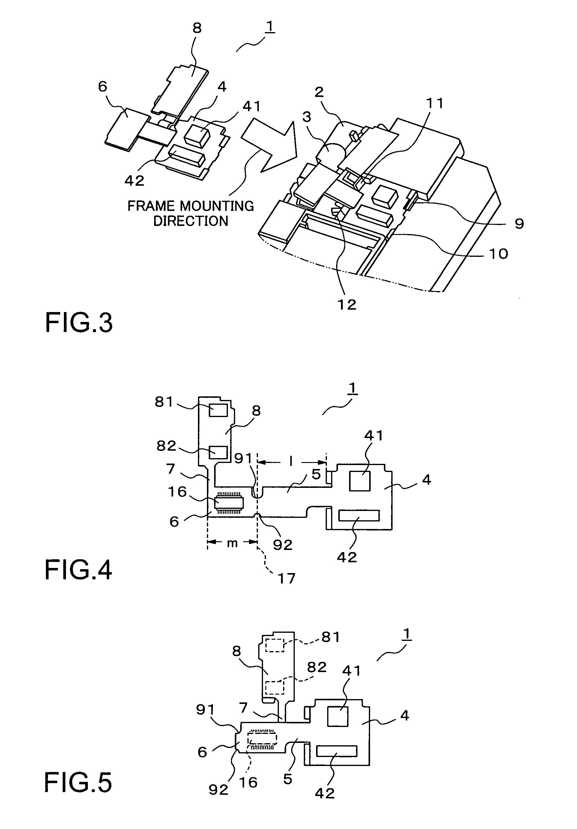
[0026] Next, exemplary embodiments according to the present invention will be described with reference to the drawings. FIG. 1 is a perspective view of an electronic circuit device using a flexible circuit board in accordance with the exemplary embodiment of the present invention. FIG. 2 is a plan view of FIG. 1. Further, FIGS. 4 and 5 each show the flexible circuit board in accordance with the exemplary embodiment of the present invention. FIG. 4 is a plan view~showing the developed flexible circuit board, and FIG. 5 is a plan view showing a state in which the flexible circuit board is folded. The electronic circuit device includes a frame 2, a main circuit board 3 mounted on the frame 2, and a flexible circuit board 1 as shown in FIGS. 4 and 5, as shown in FIGS. 1 and 2.

[0027] In FIGS. 4 and 5, the flexible circuit board according to this exemplary embodiment includes a first mounting portion 4 mounted with an electronic circuit including electronic parts 41 and 42, a second moun...


PUM


Abstract

The flexible circuit board according to the present invention includes a plurality of mounting portions which are mounted with electronic circuits respectively, a connector portion that performs signal transmission between the electronic circuit mounted on each of the mounting portions and the electronic circuit device, and coupling portions that couple the respective mounting portions to the connector portion in different directions. The flexible circuit board is mounted on the electronic circuit device in a state of being folded at a predetermined part of one of the coupling portions.

Description

BACKGROUND OF THE INVENTION [0001] 1. Field of the Invention [0002] The present invention relates to a flexible circuit board, and more particularly to a flexible circuit board provided with a plurality of electronic circuit mounting portions and to an electronic circuit device and a mobile communication terminal each including the flexible circuit board. [0003] 2. Description of the Related Art [0004] An electronic component, which is included in an electronic circuit device in compact electronic equipment, such as a mobile phone, a video camera, and the like, is mounted on a circuit board through soldering or the like. The circuit board is generally made of organic composite materials. The outer size of mounted components is limited by a substrate size. [0005] In recent years, there is a tendency in that the total size of mounted components is almost equal to an outer size of an electronic equipment in response to a demand for further reduction in size of the electronic equipment....

Claims


Application Information

Patent Timeline
IPC IPC(8): H04B1/28
CPCH05K1/189H05K3/0058H05K2201/2009
Inventor YASUI, KENICHIRO
Owner NEC CORP
Learn More