
Transparent plastic film roof and building using the same

Inactive Publication Date: 2006-06-22
ASAHI GLASS GREEN TEC
View PDF6 Cites 9 Cited by
  • Summary
  • Abstract
  • Description
  • Claims
  • Application Information

AI Technical Summary

Benefits of technology

[0006] It is an object of the present invention to solve the problems that have been caused in a conventional dual structure roof made of a transparent plastic film, in other words, to provide a roof and a building using such a roof, the roof without forming shade, the roof being capable of smoothly flowing down rain or water of melted snow or smoothly slipping down snow, being excellent in having snow melting and warm-keeping performance, of being durable, of being uniform in the thickness and the temperature distribution of a dual structure (bag-like structure), of easily assembled and constructed, of having good workability and of being inexpensive in material costs and construction cost.

Problems solved by technology

However, this device has a problem in that unless water is discharged from the spraying pipe at, e.g., nights in winter, the water is frozen to damage the spraying pipe since the spraying pipe is exposed outdoor.
This system has caused, e.g., problems that nozzles are frozen, that snow is accumulated in a tunnel shape above the gutter since nozzles fail to melt all the snow, that snow is insufficiently melted, that nozzles are clogged by dust and dirt, and that a powerful pump is needed since snow is melted by water, not air.
However, this device has caused, e.g., problems that snow is insufficiently melted since the warm air is locally blown out, a powerful pump is needed to sufficiently melt the snow, and the pipe is frozen.
In other words, the air in the pneumatic structure roof is not effective in terms of heat insulation and of keeping the house warm since the air is not warm.
When snow has piled on the roof, it is impossible to expect to obtain an effect to melt the snow.

Method used


Image

  • Transparent plastic film roof and building using the same
  • Transparent plastic film roof and building using the same
  • Transparent plastic film roof and building using the same

Examples


Embodiment Construction

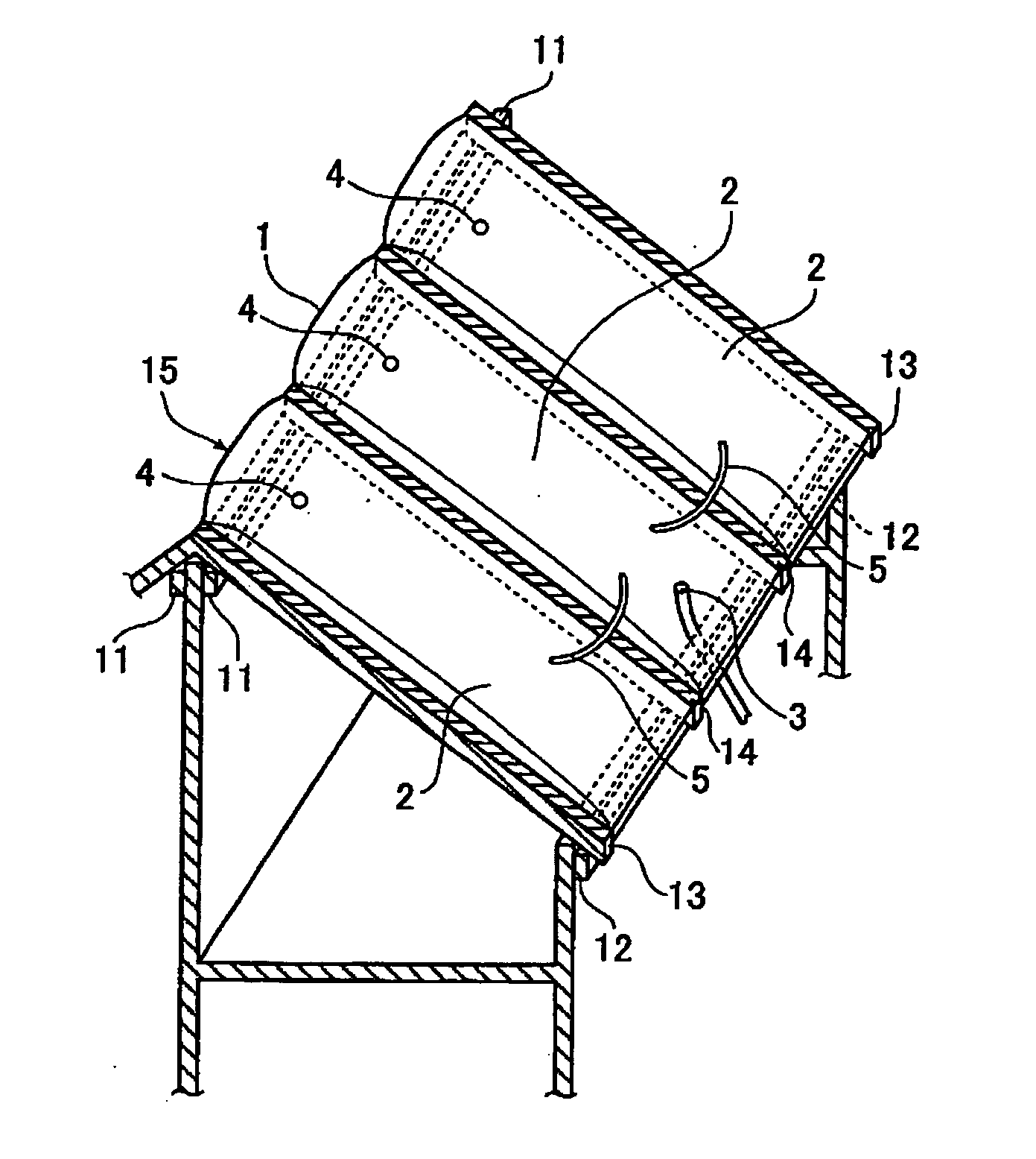
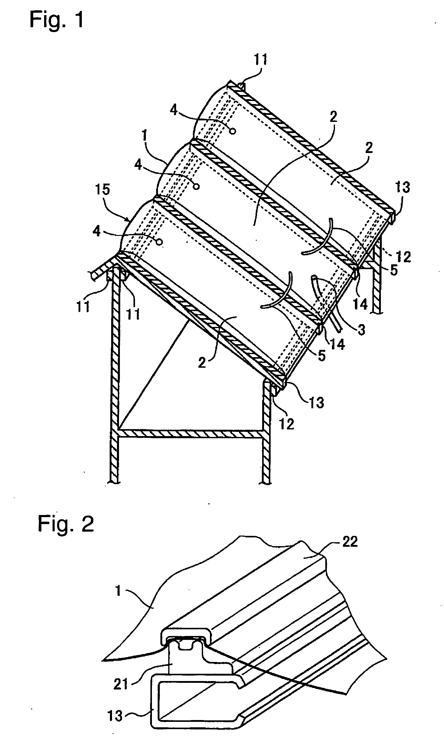
[0040] A building, which is represented by a greenhouse having a gable roof, generally has a skeleton comprising a main body constructed by assembling members, such as poles, girders, binding beams, and a gable roof constructed by assembling members, such as a ridgepole, pole plates, edge rafters, rafters, purlins, and joining hands. The respective members mainly comprise metal pipes or section bars. These members are assembled by perpendicular clamps or universal clamps and are constructed as the skeleton comprising the main body and the roof. For example, a greenhouse is constructed by causing a sheet or film to extend between and be fixed to the skeleton, the sheet or film being mainly made of a transparent resin.

[0041] The structures of the main body and the roof of a building according to the present invention are not different from those of an ordinary building. The skeleton comprising the main body and the roof may be constructed in an ordinary way. A greenhouse, which is an...


PUM


Abstract

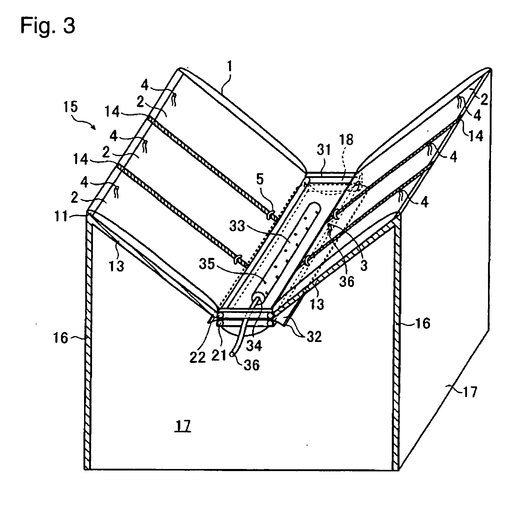
There is provided a transparent plastic film roof for a building, comprising two transparent plastic films, which are fixed to edge rafters extending from a ridgepole to a ridge plate and are formed in a bag-like structure for serving as a building roof, wherein warm air is supplied from an air supply port into the bag-like structure to maintain the bag-like structure in a tensioned state, and air in the bag-like structure is discharged from an air discharge port. There is also provided a multi-ridge building, wherein a liquid passing pipe is disposed in the same direction as long film-clamping assemblies in the vicinity of a valley portion of the multi-ridge roof formed by the two transparent plastic films, and wherein the liquid passing pipe is configured to pass warm water or warm antifreezing fluid therethrough.

Description

TECHNICAL FIELD [0001] The present invention relates to a roof having a dual structure, which is suitable for melting a pile of snow on the roof of a building or for keeping a room warm, and a building using such a roof, in particular a greenhouse. BACKGROUND ART [0002] Heretofore, as a snow melting device to be used for a greenhouse for helping to cultivate plants, there has been known a snow melting device, wherein a spraying pipe is disposed on an exterior side of the roof of a greenhouse, and groundwater or warm water is supplied and is sprayed out (e.g., JP-A-63-263021). However, this device has a problem in that unless water is discharged from the spraying pipe at, e.g., nights in winter, the water is frozen to damage the spraying pipe since the spraying pipe is exposed outdoor. [0003] There has been also known a snow removing device, wherein snow on a sloping roof is slipped down toward a gutter, and the slipped snow is melted by a snow melting means disposed near to the gutt...

Claims


Application Information

Patent Timeline
IPC IPC(8): E04D13/00A01G9/14
CPCA01G9/1415Y02A40/25A01G9/1438A01G9/24
Inventor ISISAKI, YOSHIAKI
Owner ASAHI GLASS GREEN TEC
Learn More