
Printed TTI indicators

a technology of indicators and tti, applied in the field of timetemperature integrating indicators, can solve the problems of complicated activation, insufficient colour change, and high cost of tti systems and devices

Inactive Publication Date: 2006-06-22
AVANTONE OY
View PDF27 Cites 26 Cited by
  • Summary
  • Abstract
  • Description
  • Claims
  • Application Information

AI Technical Summary

Benefits of technology

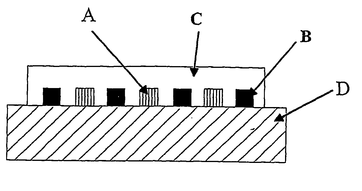
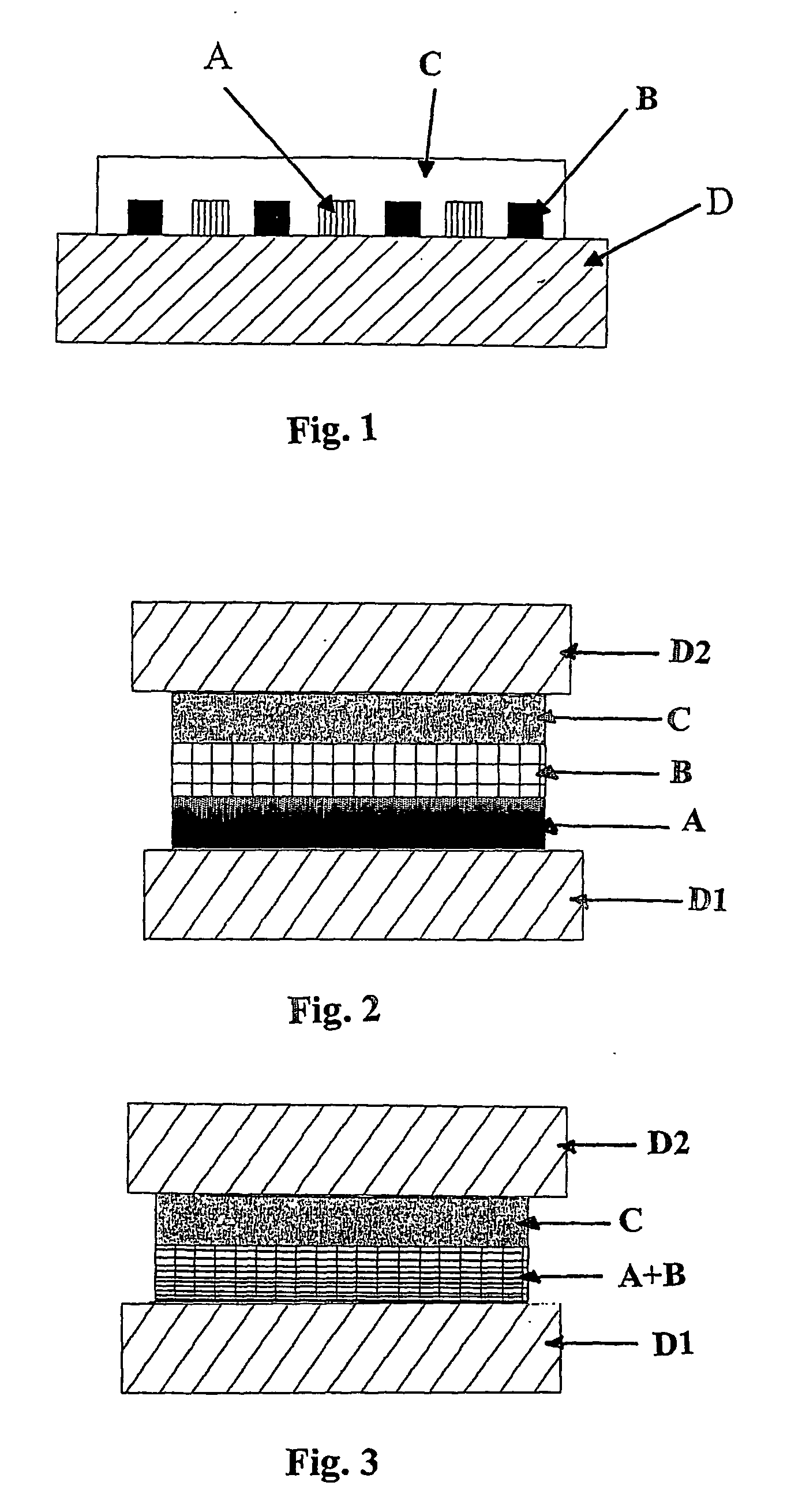
[0011] An object of the present invention is a TTI indicator, which can be directly printed on a substrate material and which can be activated at a desired moment by printing, or alternatively a TTI indicator, which can be printed between layers of a substrate material, and which can be activated at a desired moment by opening of a package containing the indicator. Said TTI indicator provides a rapid and clear indication of expiration.
[0012] A further object of the invention is a method for the manufacture of TTI indicator, which can be directly printed on a substrate material and which can be activated at a desired moment by printing, or alternatively a TTI indicator, which can be printed between layers of a substrate material, and which can be activated at a desired moment by opening of a package containing the indicator, and which indicator provides a rapid and clear indication of expiration.
[0015] It has now been realised that a TTI indicator can be easily manufactured directly on a substrate in connection with printing of the substrate, and suitably at the time of packaging of the final product, which is to be monitored. Thus the time of printing is the time of activation.
[0018] It has been noted that many of the problems and disadvantages related to the solutions according to the prior art can be avoided or at least substantially decreased by the TTI according to the invention. A TTI indicator can be easily manufactured directly on a substrate in connection with printing of the substrate, and suitably at the time of packaging of the final product, which is to be monitored. The time of printing of the TTI indicator is the time of activation of the TTI indicator.

Problems solved by technology

However, control of the reaction rate of an oxidation reaction may cause difficulties and the colour change may not be sufficiently fast.
Such TTI systems and devices are often costly to manufacture, complicated to activate and they are prone to inadvertent premature activation.

Method used


Image

  • Printed TTI indicators
  • Printed TTI indicators

Examples


Embodiment Construction

[0018] It has been noted that many of the problems and disadvantages related to the solutions according to the prior art can be avoided or at least substantially decreased by the TTI according to the invention. A TTI indicator can be easily manufactured directly on a substrate in connection with printing of the substrate, and suitably at the time of packaging of the final product, which is to be monitored. The time of printing of the TTI indicator is the time of activation of the TTI indicator.

[0019] In the alternative embodiment the TTI may be printed between layers of a substrate material. At the time of packaging of the final product or at the time of the manufacture of the packaging material / substrate the TTI indicator may suitably be printed on the inner side of the packaging material and it is then sealed between packaging material / substrate layers. The TTI is activated at a desired moment by opening of a package, containing the indicator, of the perishable product.

[0020] Th...


PUM


Abstract

The present invention relates to time-temperature integrating indicators, also known as TTI indicators, which are easily printable on substrates, such as packaging materials, and to a method for the manufacture of packaging materials comprising printed TTI indicators. The printed TTI indicator is selectively activated at the time of packaging of a perishable product or alternatively at the time of opening of the package of a perishable product.

Description

FIELD OF THE INVENTION [0001] The present invention relates to time-temperature integrating indicators, also known as TTI indicators, which are easily printable on substrates, such as packaging materials, and to a method for the manufacture of packaging materials comprising printed TTI indicators. The printed TTI indicator is selectively activated at the time of packaging of a perishable product or alternatively at the time of opening of the package of a perishable product. STATE OF THE ART [0002] Colour-changing or colour-forming temperature sensitive indicators for monitoring of handling of perishable goods are well known in the art. Such perishable goods are for example foodstuffs, pharmaceuticals, biological materials, chemical substances, coating compositions, adhesives, cosmetics, food additives, photographic supplies and vaccines. There is a growing interest for indicator systems and devices for monitoring a temperature and a time as an accumulated value of articles, which ar...

Claims


Application Information

Patent Timeline
IPC IPC(8): G01K1/02G01K3/04G01K11/16G01N31/22
CPCG01K3/04G01K11/16G01N31/229
Inventor KOIVUKUNNAS, PEKKAHURME, EERO V.
Owner AVANTONE OY
Learn More