Electrostatic atomizing device and humidifier using this

Inactive Publication Date: 2006-06-22
MATSUSHITA ELECTRIC WORKS LTD
View PDF7 Cites 37 Cited by
  • Summary
  • Abstract
  • Description
  • Claims
  • Application Information

AI Technical Summary

Benefits of technology

[0003] The present invention has been achieved to overcome the above problem and to present an electrostatically atomizing device and the humidifier using the same which can

Problems solved by technology

Therefore, it has been a problem to require mai

Method used


Image

  • Electrostatic atomizing device and humidifier using this
  • Electrostatic atomizing device and humidifier using this
  • Electrostatic atomizing device and humidifier using this

Examples


Example

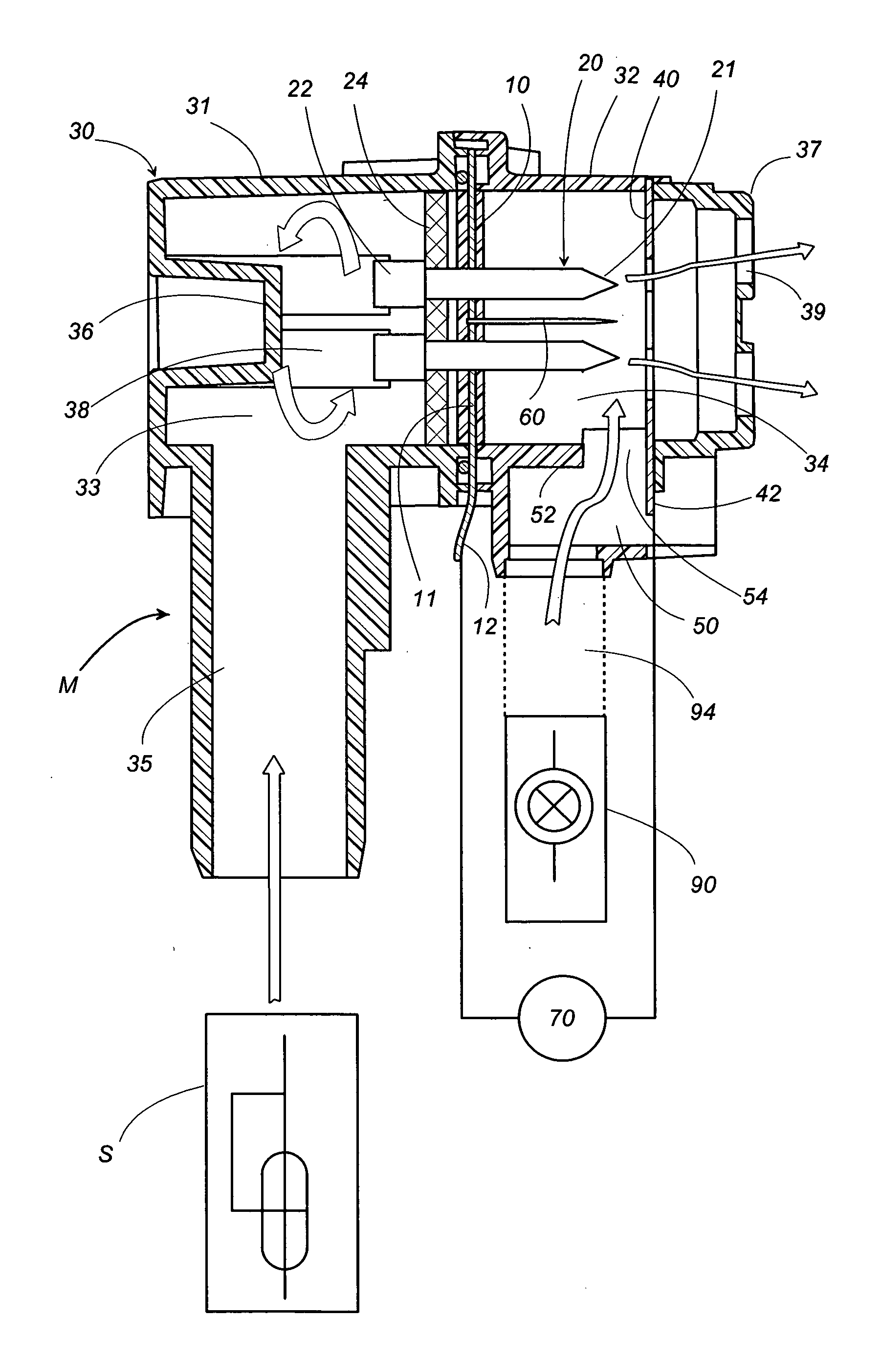
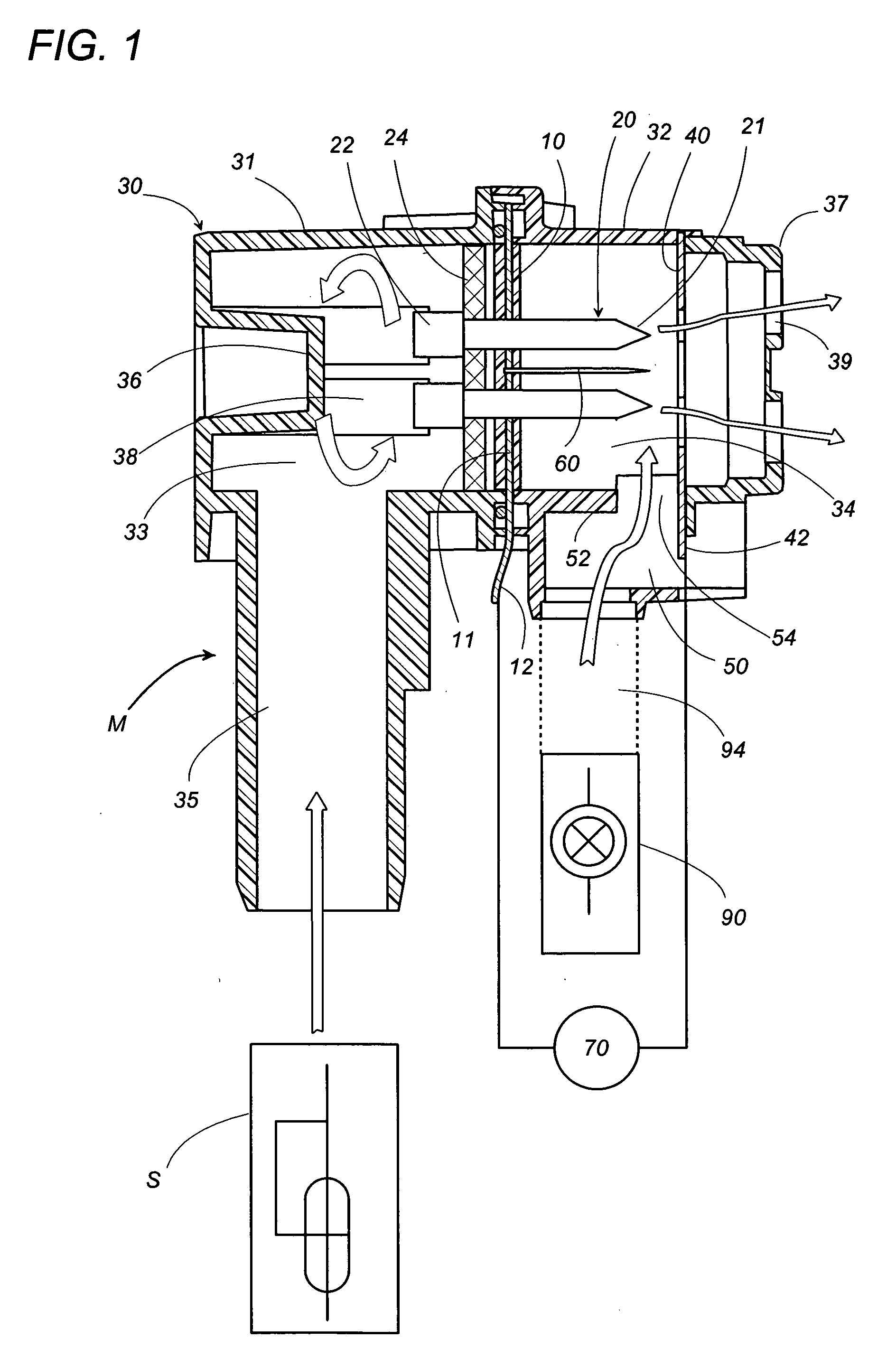
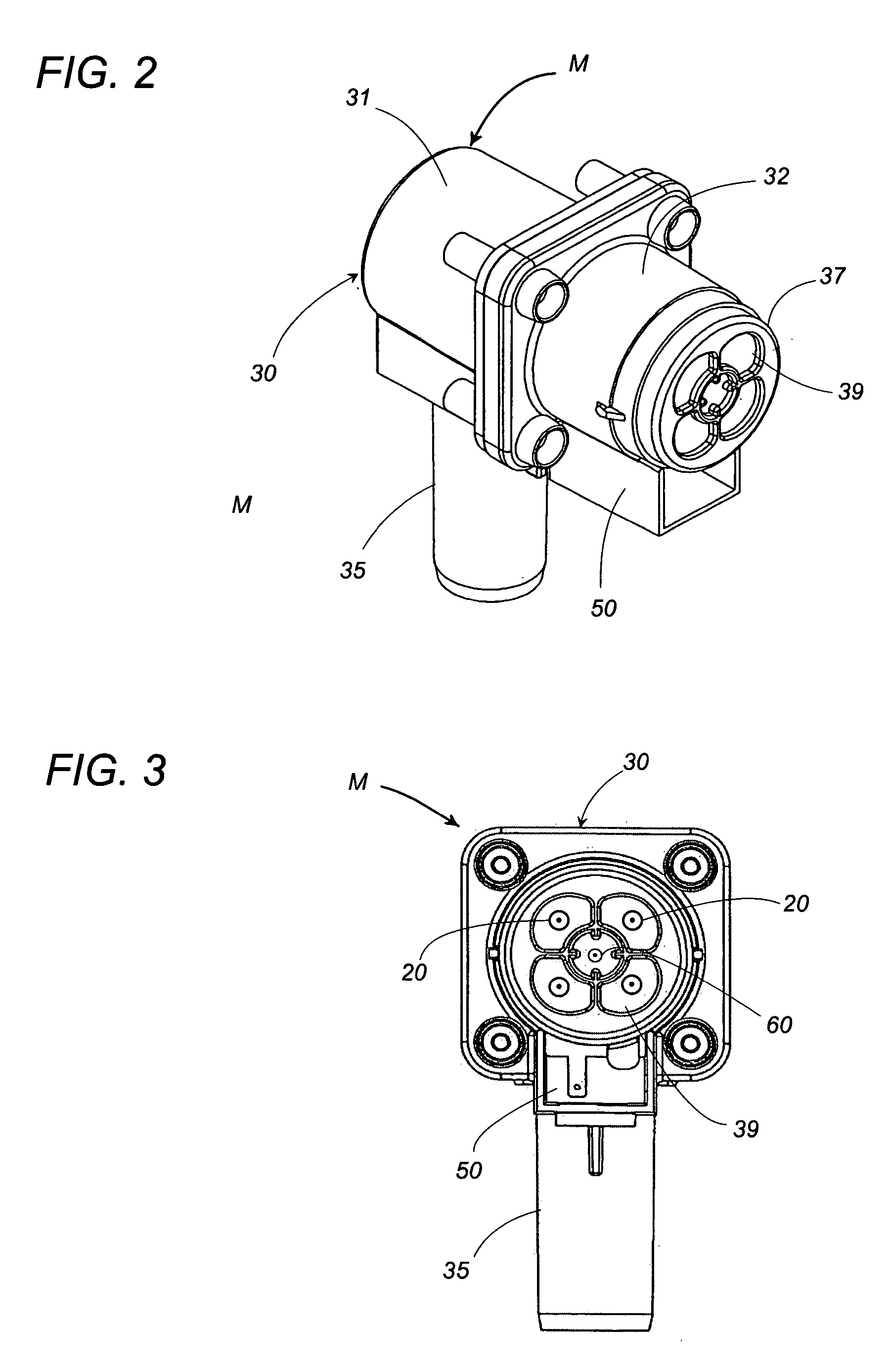
[0019] An electrostatically atomizing device in accordance with one embodiment of the present invention is configured to ionize particulate water, for example, so as to generate ionized water particles of a nanometer size, and include an atomizing unit M for electrostatically atomizing the liquid, and a steam generator S providing a steam of water. As shown in FIG. 1, the atomizing unit M includes a case 30 accommodating a plurality of capillary carriers 20. The case 30, which is made of a first tube 31 and a second tube 32 coupled to each other, has its interior space divided by a partition 10 into a condensation compartment 33 and a discharge compartment 34. The capillary carrier 20 extends through the partition 10 as being held thereby to define a liquid collecting end 22 at its portion projecting into the condensation compartment 33, while defining a discharge end 21 at its pointed end of a portion projecting into the discharge compartment 34. Extending from the first tube 31 su...


PUM

PropertyMeasurementUnit
Flow rateaaaaaaaaaa
Electric potential / voltageaaaaaaaaaa

Abstract

A carrier is used to carry a liquid, and a high voltage is applied between a discharge end of the carrier and an opposed electrode to emit ionized liquid particles. The carrier has a liquid collecting end opposite to the discharge end to feed the steam of the liquid from a steam generator, condensing the liquid therearound, and feeding the condensed liquid to the discharge end. Accordingly, even when the liquid contains cations such as those of Ca and Mg, the steam of the liquid can extremely reduce the content of these impurities, avoiding the precipitation of the impurities at the discharge end of the carrier to assure stable electrostatic atomization.

Description

TECHNICAL FIELD [0001] The present invention relates to an electrostatic atomizing device for emitting a liquid in the form of tiny ionized particles and a humidifier using the same. BACKGROUND ART [0002] Japanese Patent Publication No. 3260150 discloses a prior electrostatically atomizing device. The atomizing device utilizes capillary structure as a liquid carrier to feed the liquid to discharge end of the carrier by a capillary effect. A high voltage is applied between the carrier and a surrounding housing to emit the liquid as ionized particles from the discharge end. When the device uses the water, for example, city water, electrolytic water, PH adjusted water, mineral water, vitamin-C or amino-acid contained water, or water containing a deodorant such as fragrant oil or aromatic, minerals such as Ca or Mg possibly contained in the water will advance to the distal end of the capillary structure and react with CO2 in the air to precipitate as CaCO3 or MgO, hindering the electros...

Claims


Application Information

Patent Timeline
IPC IPC(8): B05B5/00F24F6/00B03C3/017B05B5/025B05B5/03B05B5/057B05B5/16F24F6/02F24F6/12F24F6/18
CPCB03C3/017B05B5/0255B05B5/03B05B5/057F24F6/12F24F6/14F24F6/18F24F2003/1664F24F8/20B05B5/16F24F6/00F24F6/02
Inventor AZUKIZAWA, SHIGEKAZUWAKABA, SADAHIKOSUDA, HIROSHI
Owner MATSUSHITA ELECTRIC WORKS LTD
Why Eureka
Try Eureka