Gasket assembly for joints experiencing thermally induced movement

Inactive Publication Date: 2006-06-22
CATERPILLAR INC
View PDF22 Cites 23 Cited by
  • Summary
  • Abstract
  • Description
  • Claims
  • Application Information

AI Technical Summary

Benefits of technology

[0007] One aspect of the present disclosure is directed to a gasket assembly for providing a seal between a first component, and a second component secured to the first component. The gasket assem

Problems solved by technology

The relative movement of the divider walls between the exhaust manifold and the turbocharger, if not absorbed by the gasket positioned between the two components, can cause the exhaust manifold or the manifold gasket to crack or may damage the connecting bolts used for connecting the exhaust manifold to the turbocharger.
Stainless steel gaskets with a soft inner material, such as graphite, have been used in the exhaust manifold connection, but have failed due to the expansion of the divider walls in the direction of the opposing divider wall and due to the weight of the turbocharger.
Solid stainless steel gaskets have also been used to support the weight of the turbocharger, but due to thermal expansion of the divider walls in the direction of the opposing divider wall, has led to cracking of the connecting bolts.
However, this may lead to cross-over flow of the exhaust gases leading to a potential loss in energy transfer from the engine to the turbocharger as well as erosion of the divider walls of the exhaust manifold and the turbocharger due to the increased temperature of exhaust gases produced by today's internal combustion engines.

Method used


Image

  • Gasket assembly for joints experiencing thermally induced movement
  • Gasket assembly for joints experiencing thermally induced movement
  • Gasket assembly for joints experiencing thermally induced movement

Examples


Embodiment Construction

[0014] Reference will now be made in detail to embodiments of the invention, examples of which are illustrated in the accompanying drawings. Whenever possible, the same reference numbers will be used throughout the drawings to refer to the same or like parts.

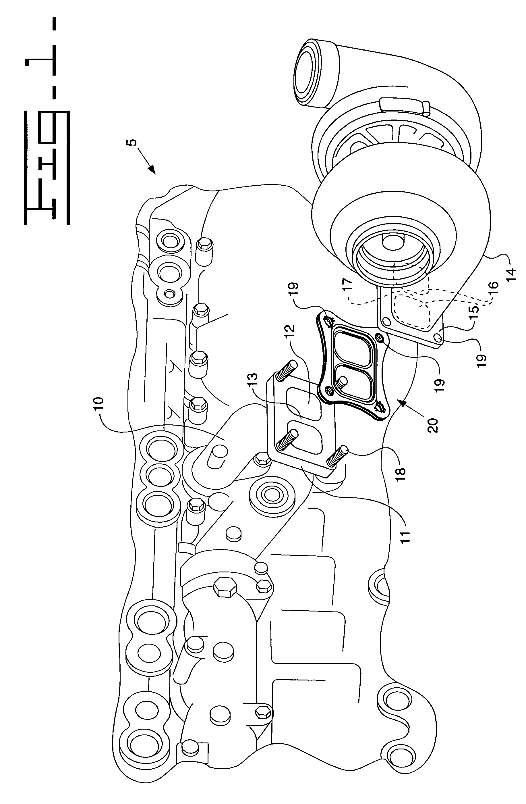
[0015]FIG. 1 shows a partial exploded view of the assembly of an exhaust manifold and a turbocharger with a gasket assembly 20 therebetween according to one embodiment of the present disclosure. An engine 5 includes a first component 10 being an exhaust manifold, a second component 14 being a turbocharger, and a gasket assembly 20 disposed therebetween. Although the first and second components 10, 14 are shown here as being an exhaust manifold and a turbocharger, the first and second components 10, 14 may be any of a number of components where a pressure tight seal may be useful or a portion of the joint may experience thermally induced movement.

[0016] As shown in FIG. 1, the gasket assembly 20 is disposed between a first comp...


PUM


Abstract

A gasket assembly for joints experiencing thermally induced movement. The gasket assembly may include a first layer, a second layer having a first portion in contact with a portion of the first layer and a second portion extending beyond contact with the first layer, and a third layer, the first portion of the second layer being in contact between the portion of the first layer and a like portion of the third layer. The gasket assembly is arranged between first and second components to accommodate thermal expansion from the first and second components.

Description

TECHNICAL FIELD [0001] This invention relates to a gasket assembly and more particularly to a gasket assembly for accommodating thermally induced gasket movement in joints of an internal combustion engine. BACKGROUND [0002] Gaskets have been widely used between joints in internal combustion engines to achieve pressure tight seals. During normal operation of the engine, cyclic temperature changes can cause thermal expansion and contraction of various components at varying rates. For example, the connection between an exhaust manifold and a turbocharger generally exhibits an increased amount of thermal expansion in the divider wall between the two openings versus the amount of expansion in the surrounding walls. The increased thermal expansion may be due to the limited divider wall thickness and limited material in which to dissipate heat thereby causing the divider wall to heat up more quickly and to higher temperatures than outlying areas. The relative movement of the divider walls ...

Claims


Application Information

Patent Timeline
IPC IPC(8): F02F11/00
CPCF16J15/0825
Inventor KERELCHUK, COLIN J.
Owner CATERPILLAR INC
Why Eureka
Try Eureka