Display device

Inactive Publication Date: 2006-06-22
SAMSUNG SDI CO LTD
View PDF3 Cites 7 Cited by
  • Summary
  • Abstract
  • Description
  • Claims
  • Application Information

AI Technical Summary

Benefits of technology

[0015] The present invention provides a display device that uses electron accelerating layers in conjunction with electrodes at different voltages to emit electron beams with energy levels sufficient to excite a gas, which emits ultraviolet rays that in tur

Problems solved by technology

A major drawback of a conventional plasma display panel and flat lamp is that they require a large amount of energy to ionize the discharge gas to generate

Method used


Image

  • Display device
  • Display device
  • Display device

Examples


Example

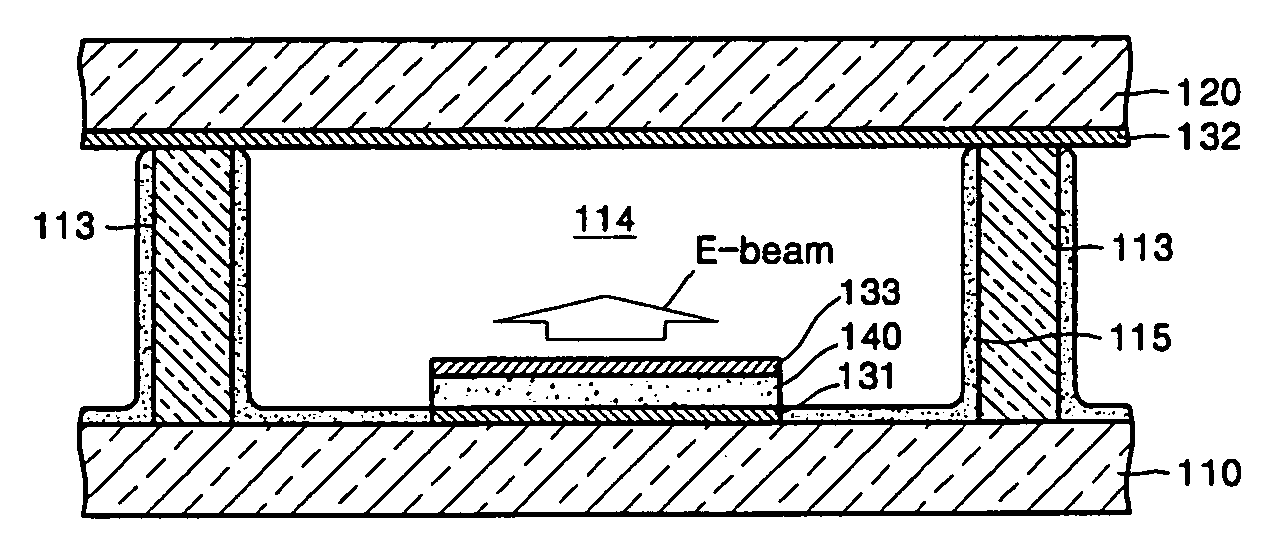
[0075]FIG. 12 shows a cross-sectional view of a flat lamp according to a fifth embodiment of the present invention. The flat lamp may be used as a backlight of an LCD.

[0076] Referring to FIG. 12, a first substrate 510 serves as a lower substrate, and a second substrate 520 serves as an upper substrate. Alternatively, the first substrate 510 may be the upper substrate and the second substrate 520 may be the lower substrate. The first substrate 510 and the second substrate 520 are arranged opposite each other with a constant distance between them. At least one cell 514 is formed between the first substrate 510 and the second substrate 520. The first substrate 510 and the second substrate 520 may be formed of transparent glass. Spacers 513 may be formed between the first substrate 510 and the second substrate 520 to define at least one cell 514. Light emitting layers 515 are coated on the inner walls of the cell 514, and a gas that may include Xe fills the cell 514.

[0077] A first ele...


PUM


Abstract

A display device uses electron accelerating layers in conjunction with electrodes at different voltages to emit electron beams with energy levels sufficient to excite a gas, which emits ultraviolet rays that in turn excite a light emitting layer to emit visible light. The use of electron accelerating layers makes it possible to excite the gas using a lower driving voltage and achieve improved luminous efficiency.

Description

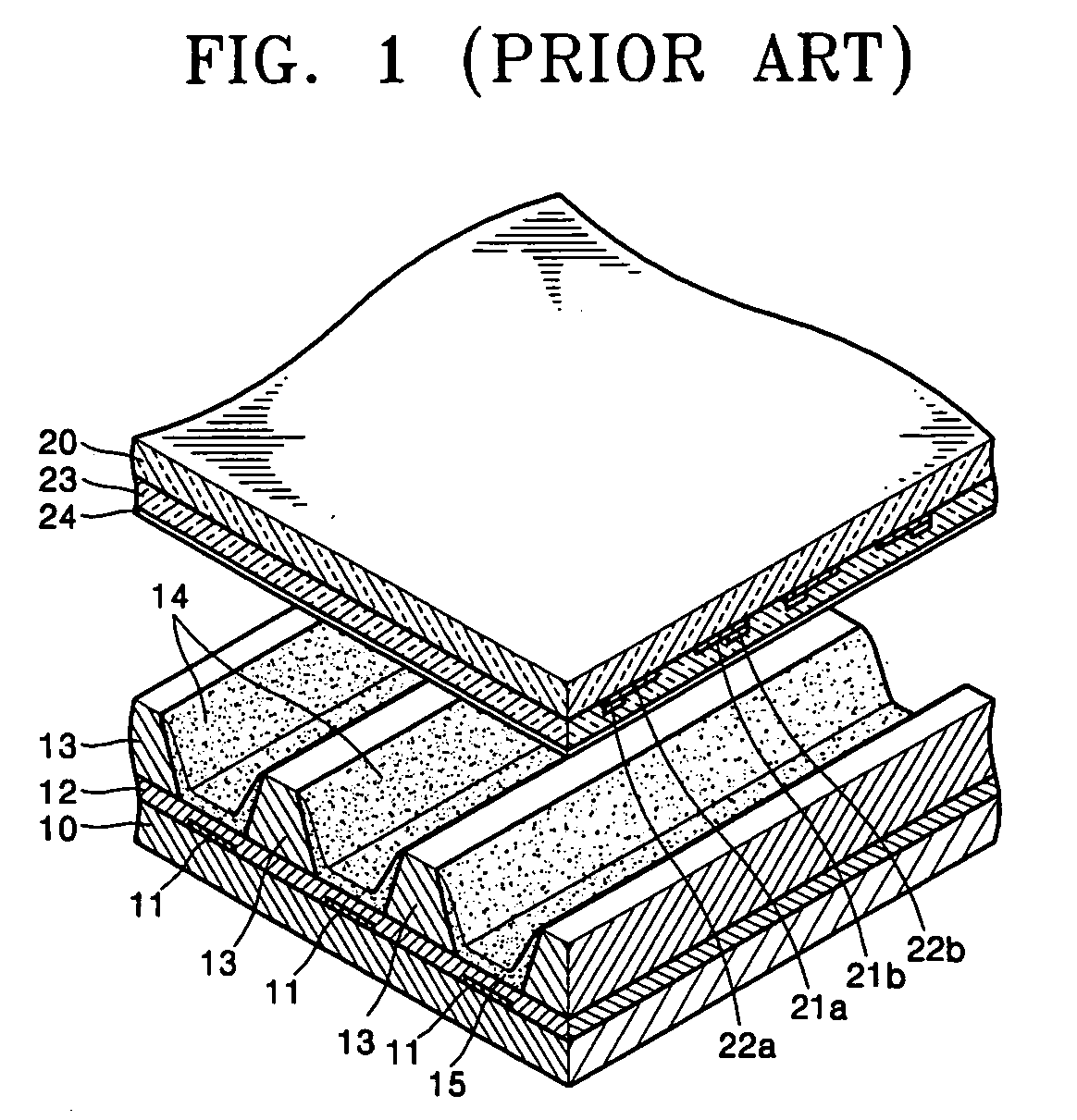
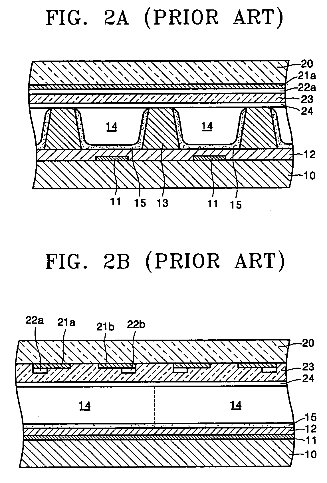
CROSS-REFERENCE TO RELATED APPLICATION [0001] This application claims priority to and the benefit of Korean Patent Application No. 10-2004-0108412, filed on Dec. 18, 2004, in the Korean Intellectual Property Office, the disclosure of which is incorporated herein in its entirety by reference. BACKGROUND OF THE INVENTION [0002] 1. Field of the Invention [0003] The present invention relates to a display device with reduced driving voltage and increased luminous efficiency. [0004] 2. Discussion of the Background [0005] Plasma display panels (PDPs) are a type of flat display device that display an image by the use of an electric discharge. PDPs enjoy wide popularity due to their exceptional brightness and wide viewing angle. PDPs emit visible light by a process where direct current (DC) or alternate current (AC) voltages are applied to electrodes with gas between them. The voltage difference excites the gas and causes it to emit ultraviolet rays. The ultraviolet rays in turn excite a pho...

Claims


Application Information

Patent Timeline
IPC IPC(8): G09G3/10H01J11/12H01J11/16H01J11/22H01J11/24H01J11/26H01J11/28H01J11/32H01J11/34H01J11/36H01J11/42H01J11/50H01J65/00
CPCG09G3/294G09G3/2983H01J11/12H01J17/066H01J17/492H01J2217/49207H01J31/12H01J11/22
Inventor HATANAKA, HIDEKAZUSON, SEUNG-HYUNKIM, YOUNG-MOLEE, SUNG-EUILEE, HO-NYEONPARK, HYOUNG-BINJANG, SANG-HUNKIM, GI-YOUNG
Owner SAMSUNG SDI CO LTD
Why Eureka
Try Eureka