Smart battery simulating system

Inactive Publication Date: 2006-06-22
UNIVERSAL SCI IND CO LTD
View PDF2 Cites 8 Cited by
  • Summary
  • Abstract
  • Description
  • Claims
  • Application Information

AI Technical Summary

Benefits of technology

[0007] Therefore, the object of the present invention is to provide a smart battery simulating system that can be

Problems solved by technology

However, since the charging/discharging operation of the smart battery is a relatively slow process, this approach for

Method used


Image

  • Smart battery simulating system
  • Smart battery simulating system

Examples


Example

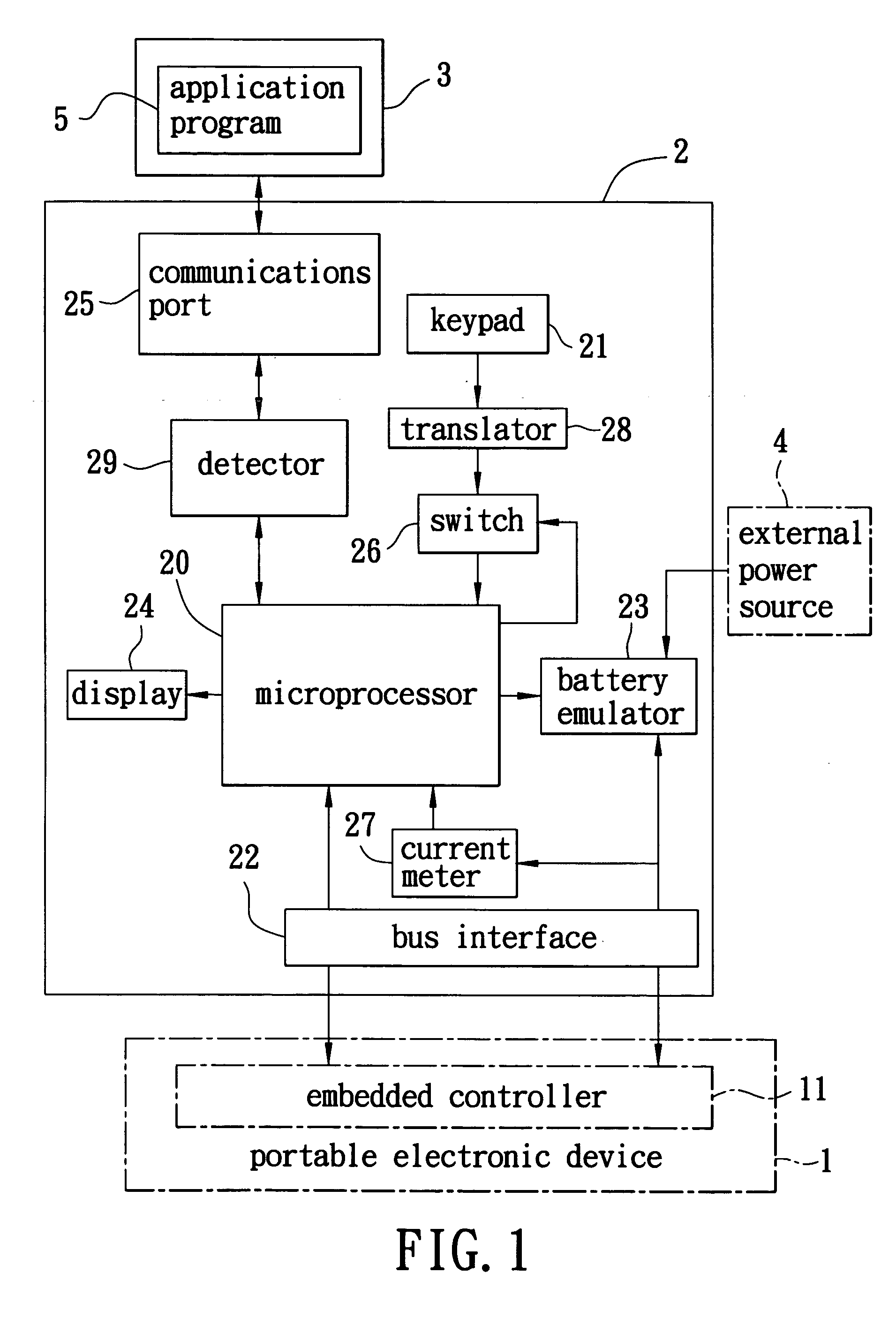
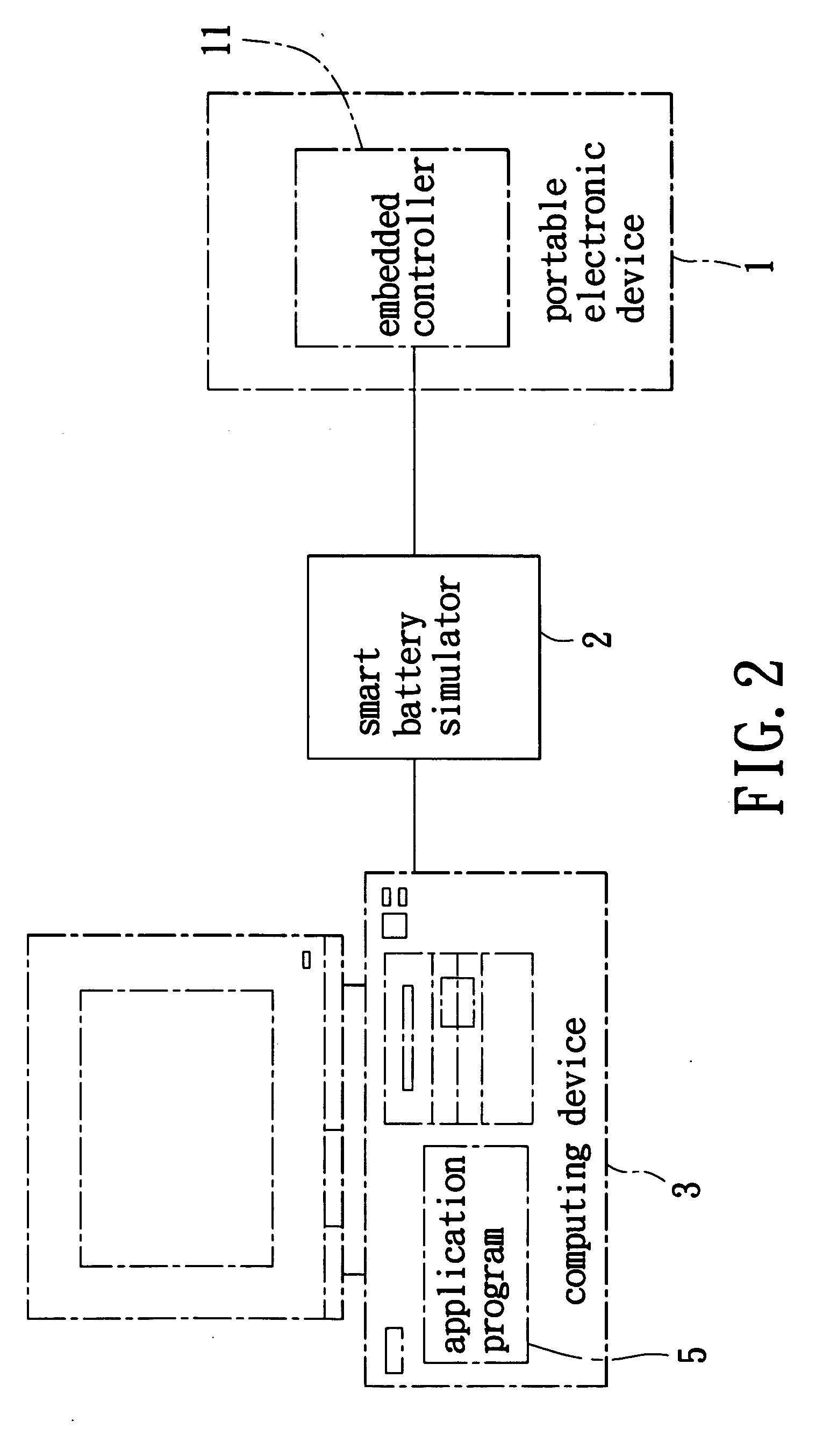
[0012] Referring to FIGS. 1 and 2, the preferred embodiment of a smart battery simulating system according to this invention is shown to include a smart battery simulator 2 and an application program 5.

[0013] The smart battery simulating system of this embodiment is applied to test response of an embedded controller 11 of a portable electronic device 1 to different battery conditions, in a manner that will be described hereinafter.

[0014] It is noted that the portable electronic device 1 may be a notebook computer, a mobile phone, or a personal digital assistant (PDA).

[0015] The smart battery simulator 2 includes a microprocessor 20, a user input unit, a communications port 25, a battery emulator 23, a current meter 27, a bus interface 22, and a display 24.

[0016] The microprocessor 20 of the smart battery simulator 2 is coupled to the embedded controller 11 of the portable electronic device 1 and a computing device 3. In this embodiment, the microprocessor 20 of the smart battery...


PUM


Abstract

A smart battery simulating system, which is applied to test response of an embedded controller of a portable electronic device to different battery conditions, includes a smart battery simulator and an application program. The smart battery simulator is coupled to the embedded controller of the portable electronic device and a computing device, and is operable so as to receive an input signal representative of battery-specific test characteristics from the computing device, and so as to generate an output signal that corresponds to the input signal and that is to be provided to the embedded controller of the portable electronic device. The application program is installed in and is executed by the computing device so as to configure the computing device to provide the input signal to the smart battery simulator when the computing device executes the application program.

Description

BACKGROUND OF THE INVENTION [0001] 1. Field of the Invention [0002] The invention relates to a battery simulating system, more particularly to a smart battery simulating system adapted for testing response of an embedded controller of a portable electronic device to different battery conditions. [0003] 2. Description of the Related Art [0004] Smart batteries are used in many existing portable electronic devices. Typically, the smart battery provides the portable electronic device with its residual capacity information. The portable electronic device includes an embedded controller that receives the residual capacity information of the battery. Thereafter, the portable electronic device performs power management in accordance with the residual capacity information received by the embedded controller of the portable electronic device. [0005] It is therefore important to test whether the embedded controller of the portable electronic device is functioning properly. A conventional metho...

Claims


Application Information

Patent Timeline
IPC IPC(8): H02J7/04
CPCG01R31/36G01R35/005H01M10/4257H01M10/48Y02E60/10
Inventor LIN, MIN-HSIUNGLIN, WEN-TANG
Owner UNIVERSAL SCI IND CO LTD
Why Eureka
Try Eureka