Method of correcting the phase difference between two input signals of a phase-locked loop and associated device

a phase-locked loop and input signal technology, applied in the direction of pulse automatic control, electric devices, etc., can solve the problem of spurious noise generated by current differences, and achieve the effect of limiting spurious noise and improving phase difference correction

Active Publication Date: 2006-06-22
STMICROELECTRONICS INT NV
View PDF3 Cites 6 Cited by
  • Summary
  • Abstract
  • Description
  • Claims
  • Application Information

AI Technical Summary

Benefits of technology

[0014] It is therefore an object of the invention to correct the foregoing problems by improving the correction of the phase difference between two input signals of a phase-locked loop, especially for small phase differences, while at the same time limiting the spurious no

Problems solved by technology

However, given that the values of each current cannot, in practice, be

Method used


Image

  • Method of correcting the phase difference between two input signals of a phase-locked loop and associated device
  • Method of correcting the phase difference between two input signals of a phase-locked loop and associated device
  • Method of correcting the phase difference between two input signals of a phase-locked loop and associated device

Examples


Embodiment Construction

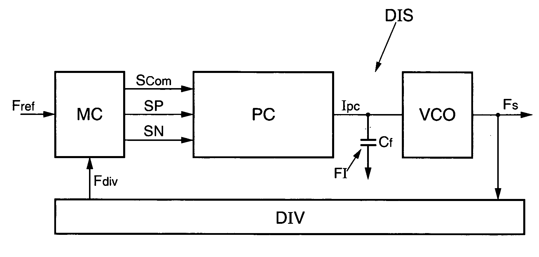
[0040]FIG. 1 illustrates an exemplary embodiment of a device DIS for correcting the phase difference between two input signals of a phase-locked loop according to the invention. The device DIS comprises a controller or control means MC receiving a reference frequency Fref at its input. The reference frequency Fref can, for example, be generated by a quartz oscillator or else by another phase-locked loop connected upstream of the device DIS. For digital television applications, Fref can be around 2.7 MHz, for example.

[0041] The controller or control means MC generates three signals at its output, an activation signal which in this example is a switching signal Scom, a signal called ‘positive signal’ SP, and a signal called ‘negative signal’ SN. An inverter (not shown) produces from the signal Scom a deactivation signal {overscore (Scom)}, which is the complementary signal to the signal Scom.

[0042] The three signals Scom, SP, and SN are delivered to a charge pump PC connected to the...


PUM


Abstract

A method for correcting the phase difference between two input signals of a phase-locked loop may include a charge pump connected to a filter. Prior to the occurrence of the first of the two input signals, a calibration phase may be carried out in which the input of the filter is disconnected from the output of the charge pump, the output voltage from the charge pump is equalized, to within a given error, with the input voltage of the filter, the amplitudes of the opposing currents flowing in the charge pump being equalized. Then, during the two respective occurrences of the two input signals, the input of the filter is reconnected to the output of the charge pump, and two phase-shifted signals that are delayed with respect to the input signals are respectively generated, in response to which the two opposing currents are, respectively and successively, interrupted, before the calibration phase is recommenced.

Description

FIELD OF THE INVENTION [0001] The invention relates to the correction of the phase difference between two signals by using a phase-locked loop. BACKGROUND OF THE INVENTION [0002] A conventional phase-locked loop is formed by a phase / frequency discriminator connected to a charge pump delivering a voltage to a voltage-controlled oscillator via a filter. The output voltage of the oscillator is delivered to the input of the phase / frequency discriminator via a feedback loop comprising, for example, a divider by N. [0003] The phase / frequency discriminator compares the phase of a reference signal that it receives at its input and the phase of the output signal from the voltage-controlled oscillator, whose frequency is divided by the divider by N of the feedback loop. In another variant, the frequency of the oscillator output signal can also be transposed by using a mixer. The reference signal can, for example, be generated by a quartz oscillator or by another phase-locked loop. Following t...

Claims


Application Information

Patent Timeline
IPC IPC(8): H03L7/00
CPCH03L7/085H03L7/087H03L7/0895
Inventor DEDIEU, SEBASTIENPAILLARDET, FREDERICPROVINS, GERALD
Owner STMICROELECTRONICS INT NV
Why Eureka
Try Eureka