Method of driving liquid crystal display and liquid crystal display

a liquid crystal display and liquid crystal technology, applied in the direction of static indicating devices, non-linear optics, instruments, etc., can solve the problems of shortening the writing period of pixel electrodes in a 1h period, affecting the selection signal, and achieving sufficient writing period , high contrast characteristics

Inactive Publication Date: 2006-06-22
MITSUBISHI ELECTRIC CORP
View PDF3 Cites 3 Cited by
  • Summary
  • Abstract
  • Description
  • Claims
  • Application Information

AI Technical Summary

Benefits of technology

[0009] It is an object of the present invention to provide a method of driving a liquid crystal display to achieve high contrast characteristics, by suppressing a lateral stripe moire in display of raster screen and ensuring a sufficient writing period to pixel electrodes, and to provide the liquid crystal display.

Problems solved by technology

In a liquid crystal display, wire resistances of gate wires and stray capacitances of the wires cause dullness in a gate selection signal outputted from a gate driver to a gate wire and delay in the selection signal.
In the conventional 2H reverse driving methods for a liquid crystal display, the lateral stripe moire can be suppressed but a writing period to pixel electrodes in a 1H period disadvantageously becomes shorter.
In such a high-resolution liquid crystal display, if the conventional driving methods are adopted, the charge writing time to the pixel electrodes, i.e., the charging time can not be sufficiently ensured, and in driving a liquid crystal panel adopting a normally white liquid crystal mode, there arises a problem of causing luminance increase in display of full black screen to reduce contrast.

Method used


Image

  • Method of driving liquid crystal display and liquid crystal display
  • Method of driving liquid crystal display and liquid crystal display
  • Method of driving liquid crystal display and liquid crystal display

Examples


Embodiment Construction

The First Preferred Embodiment

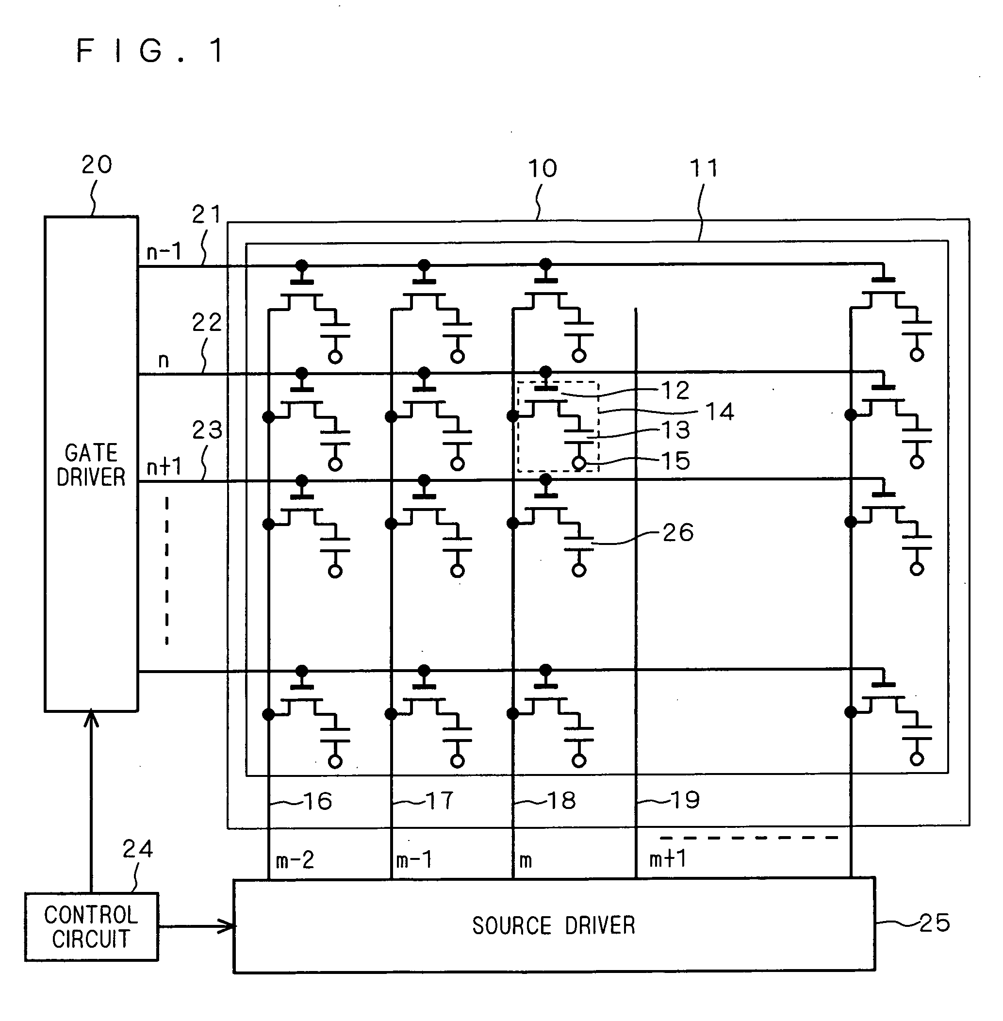
[0016]FIG. 1 is a diagram showing a liquid crystal display controlled by a driving method in accordance with the first preferred embodiment of the present invention. In FIG. 1, a normally white liquid crystal panel 10 has a structure in which an active matrix substrate 11 having a matrix arrangement consisting of a plurality of source wires (source interconnection lines) 16, 17, 18 and 19 and a plurality of gate wires (gate interconnection lines) 21, 22 and 23 which intersect each other and a not-shown opposed substrate which is opposite to the substrate 11 are bonded with a gap therebetween and in the gap, a not-shown liquid crystal is held. A pixel portion 14 indicated by broken line is placed at the intersection of the source wires 18 and 19 and the gate wires 22 and 23 and has a TFT 12 and a pixel electrode 13 as a switching device, and the gate wire 22, the source wire 18 and the pixel electrode 13 are connected to a gate, a source and a drain of ...


PUM


Abstract

In a 2H reverse driving method or the like as a driving method for a liquid crystal display, it is set that a time period from the time when the polarity of a data signal is reversed to the time when a gate selection signal is turned off should be equal to a period while a gate selection signal is in an ON period, and a period from the time when the gate selection signal is turned off to the time when the data signal is changed to a data output corresponding to a pixel selected by the gate selection signal is set equal to or shorter than a period from the time when the gate selection signal is turned off to the time when the polarity of the data signal is reversed.

Description

BACKGROUND OF THE INVENTION [0001] 1. Field of the Invention [0002] The present invention relates to a selection signal for controlling conduction of a plurality of switching devices connected to a plurality of pixel electrodes, respectively, in a liquid crystal display, a driving method for controlling supply of data signals to a plurality of pixels through these switching devices, and a liquid crystal display provided with a control circuit for performing a control by the driving method. [0003] 2. Description of the Background Art [0004] In a liquid crystal display, wire resistances of gate wires and stray capacitances of the wires cause dullness in a gate selection signal outputted from a gate driver to a gate wire and delay in the selection signal. As countermeasures against the above well known is a driving method for setting the time when the gate selection signal is changed from ON to OFF (hereinafter, referred to as “turn-off”) and the time when the signal is changed from OF...

Claims


Application Information

Patent Timeline
Patent Type & Authority Applications(United States)
IPC IPC(8): G09G3/36
CPCG09G3/3614G09G3/3648G09G2310/08G09G2320/0223G09G2320/0233G09G3/36G02F1/133G09G3/20
Inventor TERAGAKI, TOMOYANAKANISHI, KUNIFUMIMINAMI, AKIHIRO
Owner MITSUBISHI ELECTRIC CORP
Why Eureka
Try Eureka