Plasma display device

A display device, plasma technology, applied in the direction of identification device, static indicator, solid cathode parts, etc., can solve the problems of inefficient use of animation drive margin, deterioration of optical characteristics, panel heat release, etc., to improve contrast characteristics, heat reduction, and margin improvement effects

Inactive Publication Date: 2007-06-20
LG ELECTRONICS INC
View PDF0 Cites 0 Cited by
  • Summary
  • Abstract
  • Description
  • Claims
  • Application Information

AI Technical Summary

Problems solved by technology

Therefore, when designing the driving waveform, in the prior art, the driving waveform is determined based on the still image, and the movie is also driven with the same waveform, so there are problems in the playback of the movie: heat generation in the panel, contrast, etc. Deterioration of optical characteristics, excessive power consumption
Therefore, there is a problem that the driving margin in the animation cannot be used efficiently in the existing technology

Method used


Image

  • Plasma display device
  • Plasma display device
  • Plasma display device

Examples


Embodiment Construction

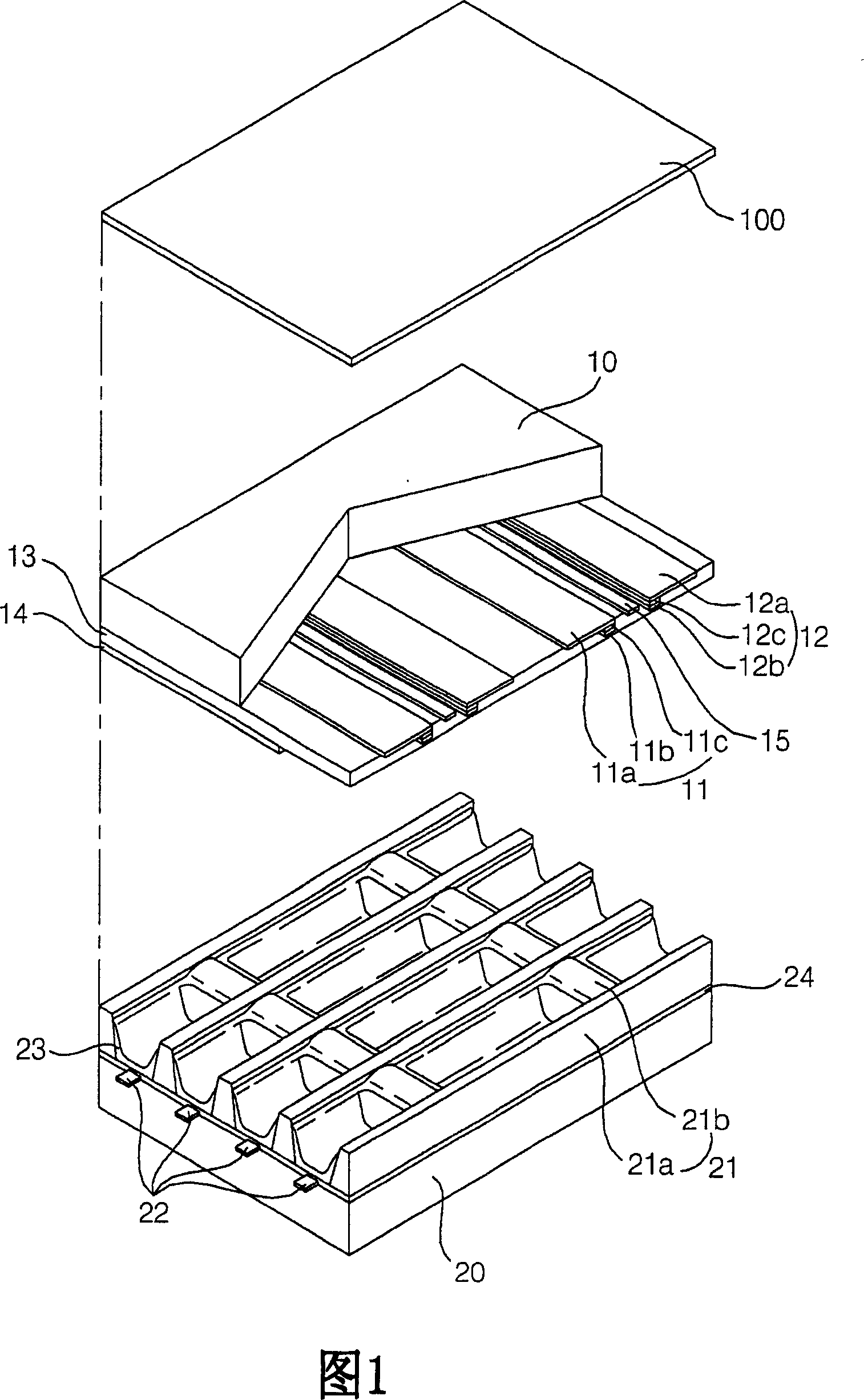
[0020] Preferred embodiments of the present invention will be described in detail below with reference to the accompanying drawings 1 to 6 . FIG. 1 is a perspective view showing an embodiment of a plasma display panel according to the present invention.

[0021] As shown in FIG. 1 , the plasma display panel includes scan electrodes 11 and sustain electrodes 12 as sustain electrode pairs formed on an upper substrate 10 , and address electrodes 22 formed on a lower substrate 20 .

[0022] The sustain electrode pair 11, 12 generally includes transparent electrodes 11a, 12a formed of Indium-Tin-Oxide (ITO) and bus electrodes 11b, 12b, and the bus electrodes 11b, 12b may be formed of silver (Ag), Metals such as chromium (Cr) or laminated type of chromium / copper / chromium (Cr / Cu / Cr), laminated type of chromium / aluminum / chromium (Cr / Al / Cr). The bus electrodes 11b, 12b are formed on the transparent electrodes 11a, 12a, and function to reduce a voltage drop through the transparent elec...


PUM


Abstract

The present invention provides a plasma display apparatus which can improve a driving waveform and enhance driving margin and optical characteristic when motion images are outputted. The plasma display apparatus includes a first electrode formed in a panel, and a first electrode driver configured to apply a driving waveform to the first electrode, wherein the first electrode driver applies different driving waveforms when motion images are output and when still images are output. In the plasma display apparatus constructed as described above according to the present invention, images are divided into still images and motion images. In the motion images, as a motion change increases, a driving waveform is varied by decreasing the number of set-up signals or sustain pulses, or by lowering a set-up voltage. Accordingly, the distortion of an image occurring as waveforms are varied can be minimized. Furthermore, there are advantages in that the margin of a driving signal can be enhanced, heat generated from a panel can be reduced, and damage to the panel can be prevented. In particular, there is an advantage in that a contrast characteristic of an image can be improved.

Description

technical field [0001] The present invention relates to a plasma display device, in particular to a plasma display device which improves driving waveforms and improves driving margin and optical characteristics during animation output. Background technique [0002] A plasma display panel (Plasma Display Panel, hereinafter referred to as PDP) is a device as follows: a predetermined voltage is applied to an electrode provided in a discharge space to cause a discharge, and the phosphor is excited by the plasma generated during the gas discharge, thereby displaying An image including text or graphics has the following advantages: it is easy to realize large-scale and light weight, light and thin plane, can provide wide viewing angles of up, down, left, and right, and realize full color and high brightness. [0003] In this case, the driving waveform of the plasma display device is generally determined based on a still image. Therefore, when designing the driving waveform, in th...

Claims


Application Information

Patent Timeline
Patent Type & Authority Applications(China)
IPC IPC(8): H01J17/49H01J17/04G09F9/313G09G3/28G09G3/288G09G3/20G09G3/291G09G3/292G09G3/294G09G3/296G09G3/298
CPCG09G2330/045G09G3/2927G09G3/2022G09G2330/021G09G2360/16G09G2320/066G09G2320/103G09G3/291G09G3/296
Inventor 尹相辰
Owner LG ELECTRONICS INC
Why Eureka
Try Eureka