Method and apparatus for combining a targetless optical measurement function and optical projection of information

a targetless optical measurement and information technology, applied in the field of metals, can solve the problems of introducing additional costs into the manufacturing operation, manufacturing personnel's errors when using factory aids, and the wear and tear of the factory aids, so as to reduce the cost of the system

Active Publication Date: 2006-06-22
THE BOEING CO
View PDF26 Cites 92 Cited by
  • Summary
  • Abstract
  • Description
  • Claims
  • Application Information

AI Technical Summary

Benefits of technology

[0010] Embodiments of the present invention provide a system and method for targetless optical measurement and optical information projection. According to the present invention, one system is used instead of two separate systems for measuring and for projecting information. As a result, position of one system does not have to be calibrated relative to the other system. This can eliminate a major source of error in conventional systems between initial measurement of a part and relative positioning of projection of a pattern or information. This can also reduce cost of the system because elements are shared between measurement and projection functions.
[0011] Also, measurements can be made without use of retro-reflectors. As a result, embodiments of the present invention advantageously may be used to make measurements and project information on-line as part of the production process. This can cut flow time for assembly while enhancing accuracy and reducing undesired rework.

Problems solved by technology

In manufacturing operations, complicated assemblies and contoured parts are often mated to other complicated assemblies and parts.
These factory aids are subject to wear and tear and, as a result, are replaced from time-to-time.
Also, errors may be made by manufacturing personnel when using the factory aids.
All of these aspects of the factory aids introduce additional costs into the manufacturing operation.
However, this technique only gives one point indicating the location of the part.
Typical laser trackers are not able to directly measure the coordinates of the mounted hardware relative to the reference targets or other mounted hardware.
This is because typical laser trackers only measure off retro-reflective targets, and because the line-of-sight path between the laser and the retro-reflective targets is blocked.
Use of retro-reflective targets introduces additional time and labor costs into manufacturing operations.
Because of their angle-sensitivity and time requirements, retro-reflectors are not able to be used to make measurements in a production line as part of the production process.
Further, laser trackers cannot provide the factory aid function described above, such as would provide information about how the part should be oriented.
However, there is an unmet need in the art for a system and method for performing measurements without retro-reflectors and for projecting information with the same system.

Method used


Image

  • Method and apparatus for combining a targetless optical measurement function and optical projection of information
  • Method and apparatus for combining a targetless optical measurement function and optical projection of information
  • Method and apparatus for combining a targetless optical measurement function and optical projection of information

Examples


Embodiment Construction

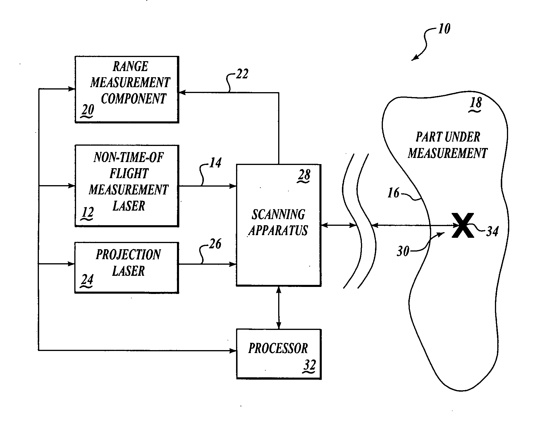
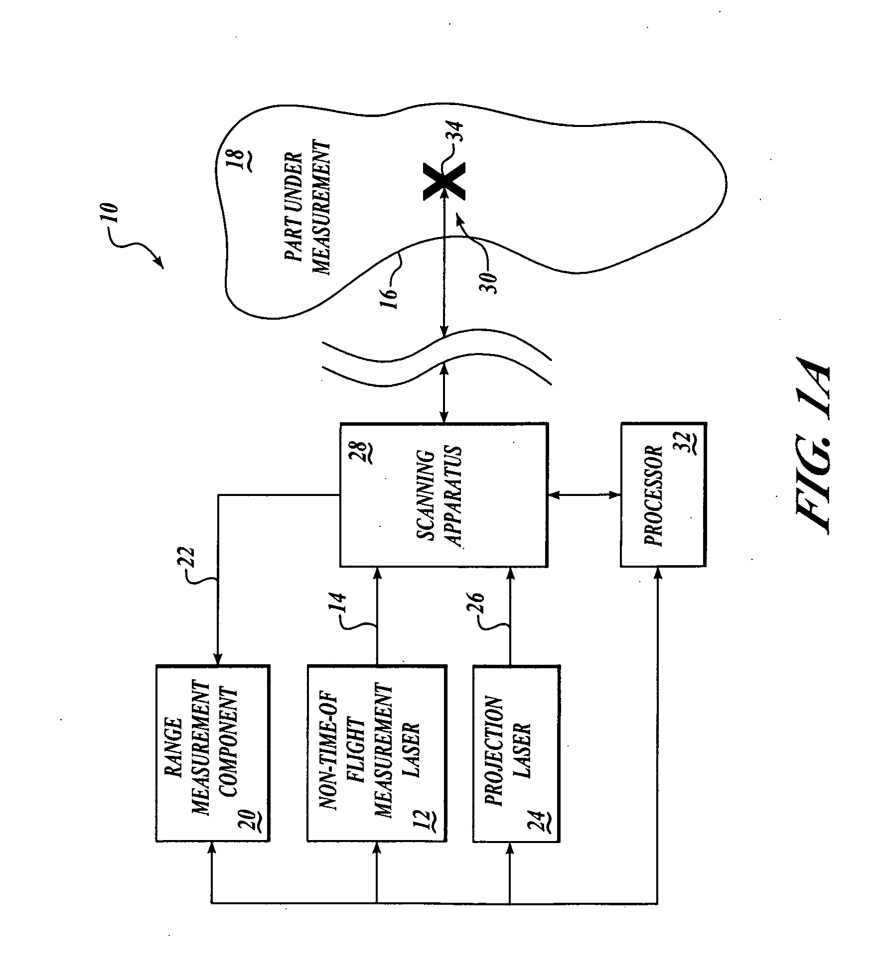
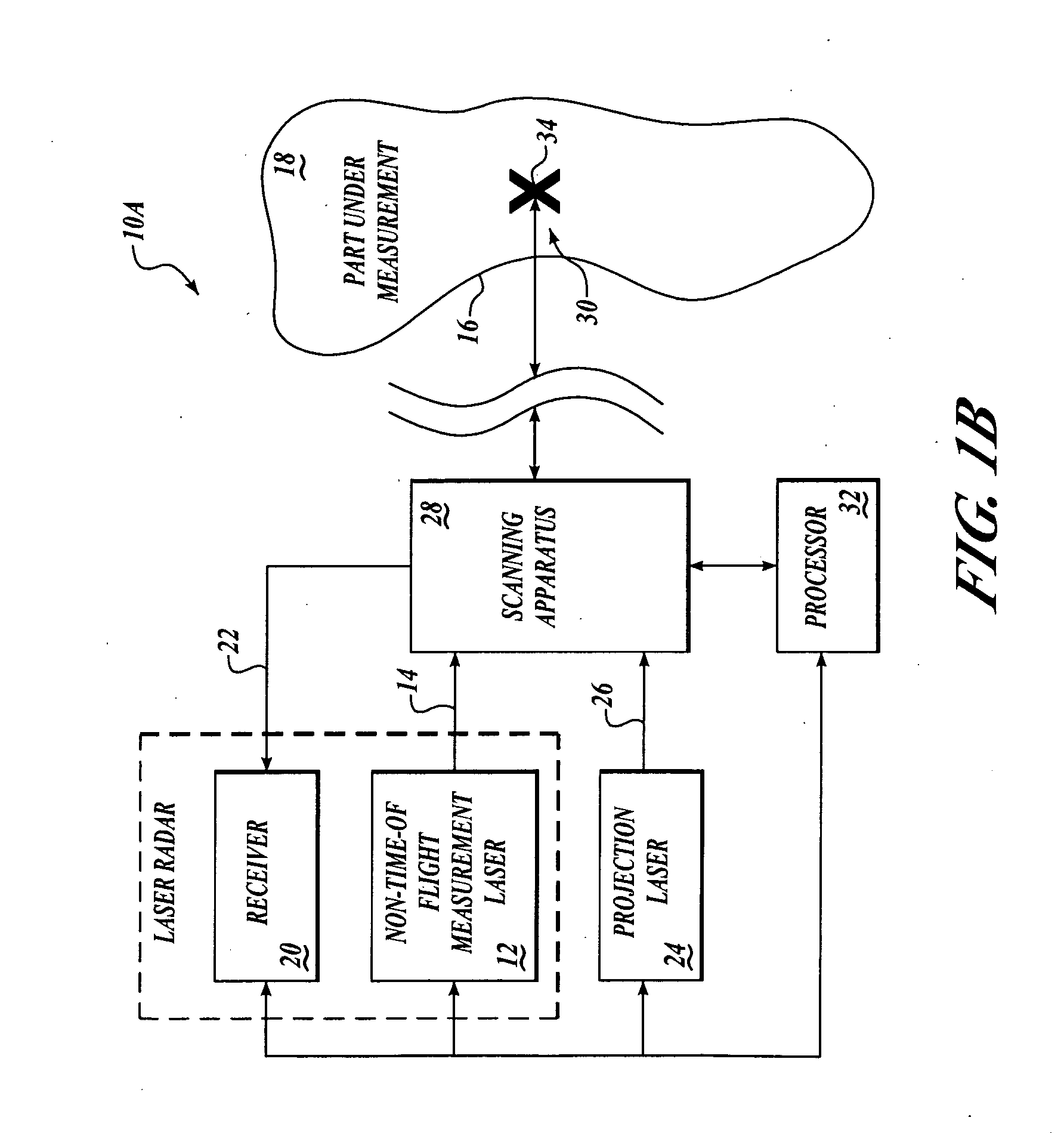
[0025] Embodiments of the present invention provide a system and method for targetless optical measurement and optical information projection. According to the present invention, one system is used instead of two separate systems for measuring and for projecting information. As a result, position of one system does not have to be calibrated relative to the other system. This can eliminate a major source of error in conventional systems between initial measurement of a part and relative positioning of projection of a pattern or information. This can also reduce cost of the system because elements are shared between measurement and projection functions. Also, measurements can be made without use of retro-reflectors. As a result, embodiments of the present invention advantageously may be used to make measurements and project information on-line as part of the production process.

[0026] By way of overview and referring to FIG. 1A, an exemplary embodiment of the present invention provide...


PUM


Abstract

Systems and methods are provided for targetless optical measurement and optical information projection. A non-contact optical measurement device is provided for determining at least one of position and orientation of a workpiece. A projector is provided for projecting a part definition on the workpiece. Advantageously, beams from the non-contact optical measurement device and the projector pass through common optics.

Description

FIELD OF THE INVENTION [0001] This invention relates generally to metrology and, more specifically, to optical measurement systems and methods. BACKGROUND OF THE INVENTION [0002] In manufacturing operations, complicated assemblies and contoured parts are often mated to other complicated assemblies and parts. A variety of techniques are currently used to locate the assemblies and parts for mating. [0003] For example, some assembly techniques use factory aids such as templates that are made out of paper, Mylarm, or the like to find reference targets for accurately placing smaller parts on larger parts. These factory aids are subject to wear and tear and, as a result, are replaced from time-to-time. The factory aids must be replaced when engineering changes are made. Also, errors may be made by manufacturing personnel when using the factory aids. All of these aspects of the factory aids introduce additional costs into the manufacturing operation. [0004] In other assembly techniques, a ...

Claims


Application Information

Patent Timeline
Patent Type & Authority Applications(United States)
IPC IPC(8): G01B11/14
CPCG01B11/002G01B11/026G01B11/245
Inventor CLAIR, JONATHAN M. SAINTVOTH, MITCHELL D.SOREIDE, DAVID C.SHERMAN, WILLIAM D.
Owner THE BOEING CO
Why Eureka
Try Eureka