Supercharge Your Innovation With Domain-Expert AI Agents!

Memory system and method for strobing data, command and address signals

a data and command and address technology, applied in the field of memory system and methods, can solve the problems of data signals not being able to adequately track the variations in the propagation time of transmitted command, address or data signals, and not being without limitations

Active Publication Date: 2006-06-22
MICRON TECH INC
View PDF38 Cites 3 Cited by
  • Summary
  • Abstract
  • Description
  • Claims
  • Application Information

AI Technical Summary

Benefits of technology

This approach ensures accurate capture of command, address, and data signals during their valid period, even at high operating speeds and varying propagation times, by matching signal transitions and minimizing delays, thus improving data transfer efficiency in memory systems.

Problems solved by technology

Therefore, it is generally not practical to use a fixed timing circuit to generate a quadrature strobe signal from the system clock signal.
Although these closed loop circuits can accurately generate a quadrature strobe signal based on the system clock signal over a substantial range of frequencies of the system clock signal, they are not without their limitations.
For example, the propagation delays of the command, address and data signals coupled between a memory controller and a memory device may vary to such an extent that a quadrature strobe signal generated from the system clock can no longer capture these signals during their valid period or eye.
However, the phase of the quadrature strobe signal generated from the strobe signal coupled with the transmitted command, address or data signals may not adequately track variations in the propagation times of the transmitted command, address or data signals.
Therefore, even a quadrature strobe signal generated from a strobe signal transmitted with the command, address or data signals may fail to capture these signals during their valid period or eye.
Capturing command, address and data signals during the eye becomes even more difficult in memory devices and memory controllers in which several bits of data are serially coupled from an external terminal each clock period.

Method used


Image

  • Memory system and method for strobing data, command and address signals
  • Memory system and method for strobing data, command and address signals
  • Memory system and method for strobing data, command and address signals

Examples


Embodiment Construction

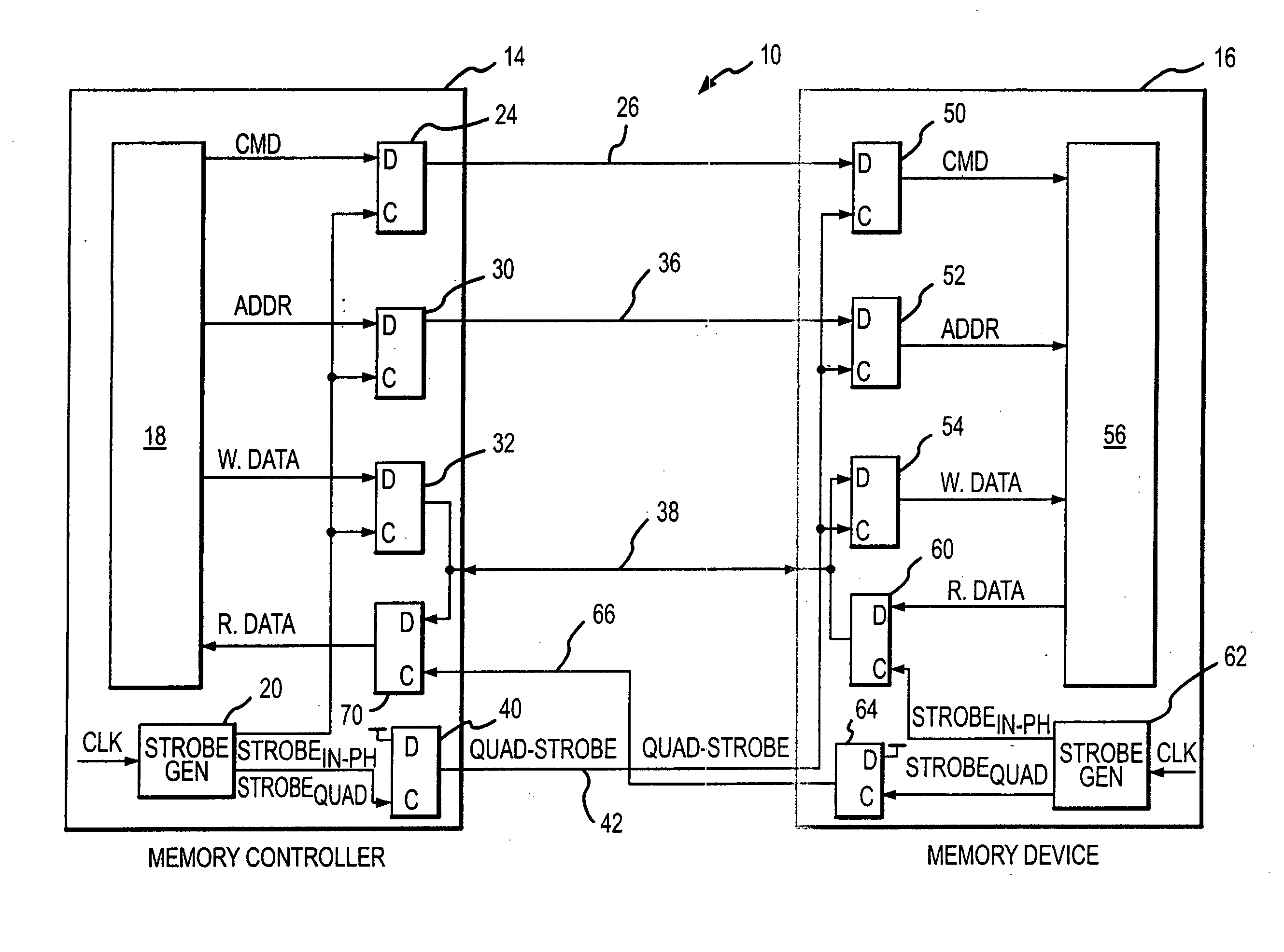
[0012] A memory system 10 according to one embodiment of the invention is shown in FIG. 1. The memory system includes a memory controller 14 coupled to a memory device 16, such as a synchronous dynamic random access memory (“SDRAM”). In addition to the components normally found in a conventional memory controller, which are designated by the reference numeral 18, the memory controller 14 includes a strobe signal generating circuit 20 that generates an in-phase strobe signals STROBEIN-PH and a quadrature strobe signal STROBEQUAD from a system clock signal CLK. The STROBEIN-PH signal is substantially in phase with the CLK signal while the STROBEQUAD is delayed substantially 90 degrees from the CLK signal. Although the CLK signal is a continuous free-running signal, the STROBEIN-PH signal and the STROBEQUAD signal are generated from the CLK signal only when command, addresses or write data are being coupled from the memory controller 14.

[0013] The STROBEIN-PH signal is coupled to the ...


PUM


Abstract

A memory system couples command, address or write data signals from a memory controller to a memory device and read data signals from the memory device to the memory controller. A respective strobe generator circuit in each of the memory controller and the memory device each generates an in-phase strobe signal and a quadrature strobe signal. Command, address or write data signals stored in respective output latches in the memory controller are clocked by the in-phase signals from the internal strobe generator circuit. These command, address or write data signals are latched into input latches in the memory device by the quadrature strobe signal coupled from the memory controller to the memory device. In substantially the same manner, read data signals are coupled from the memory device to the memory controller using the in-phase and quadrature strobe signals generated by the internal strobe generator circuit.

Description

TECHNICAL FIELD [0001] This invention relates to memory system and methods, and, more particularly, to a system and method for accurately latching data, command and address signals coupled between a memory controller and a memory device. BACKGROUND OF THE INVENTION [0002] Command, address and write data signals are typically coupled from a memory controller or other device to memory devices, such as synchronous random access memory (“SDRAM”) devices. These command, address and write data signals are typically transmitted in synchronism with a system clock signal. Similarly, read data signals are typically coupled from memory devices to a memory controller or other device in synchronism with the system clock signal. In some cases, the memory devices or memory controller may couple a strobe signal between the memory devices and memory controller along with the command, address and data signals. The system clock signal or strobe signal derived from the system clock signal is used to “c...

Claims


Application Information

Patent Timeline
Patent Type & Authority Applications(United States)
IPC IPC(8): G11C7/00
CPCG11C7/1006G11C7/1078G11C7/1087G11C7/109G11C7/22G11C7/222G06F13/42G11C7/00G11C7/10G11C8/00
Inventor LIN, FENGKEETH, BRENTJOHNSON, BRIANLEE, SEONG-HOON
Owner MICRON TECH INC
Features
  • R&D
  • Intellectual Property
  • Life Sciences
  • Materials
  • Tech Scout
  • Unparalleled Data Quality
  • Higher Quality Content
  • 60% Fewer Hallucinations
Learn More