

High efficiency encoder and video information recording/reproducing apparatus
a video information and encoder technology, applied in the field of digital signal recording/reproducing apparatus, can solve the problems of deteriorating image quality immediately after scene change, increasing the total amount of codes, increasing the size of field memory or frame memory, etc., and achieving the effect of reducing the hardware siz
- Summary
- Abstract
- Description
- Claims
- Application Information
AI Technical Summary
Benefits of technology
Problems solved by technology
Method used
Image

Examples
embodiment 1
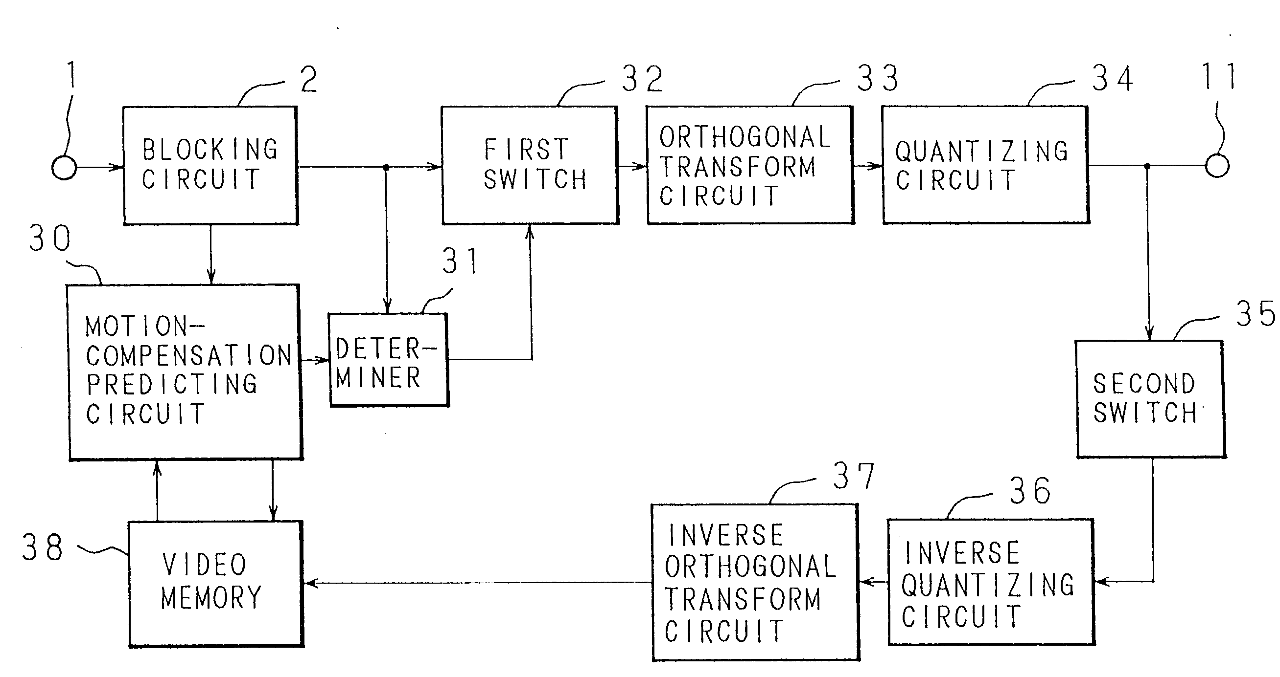
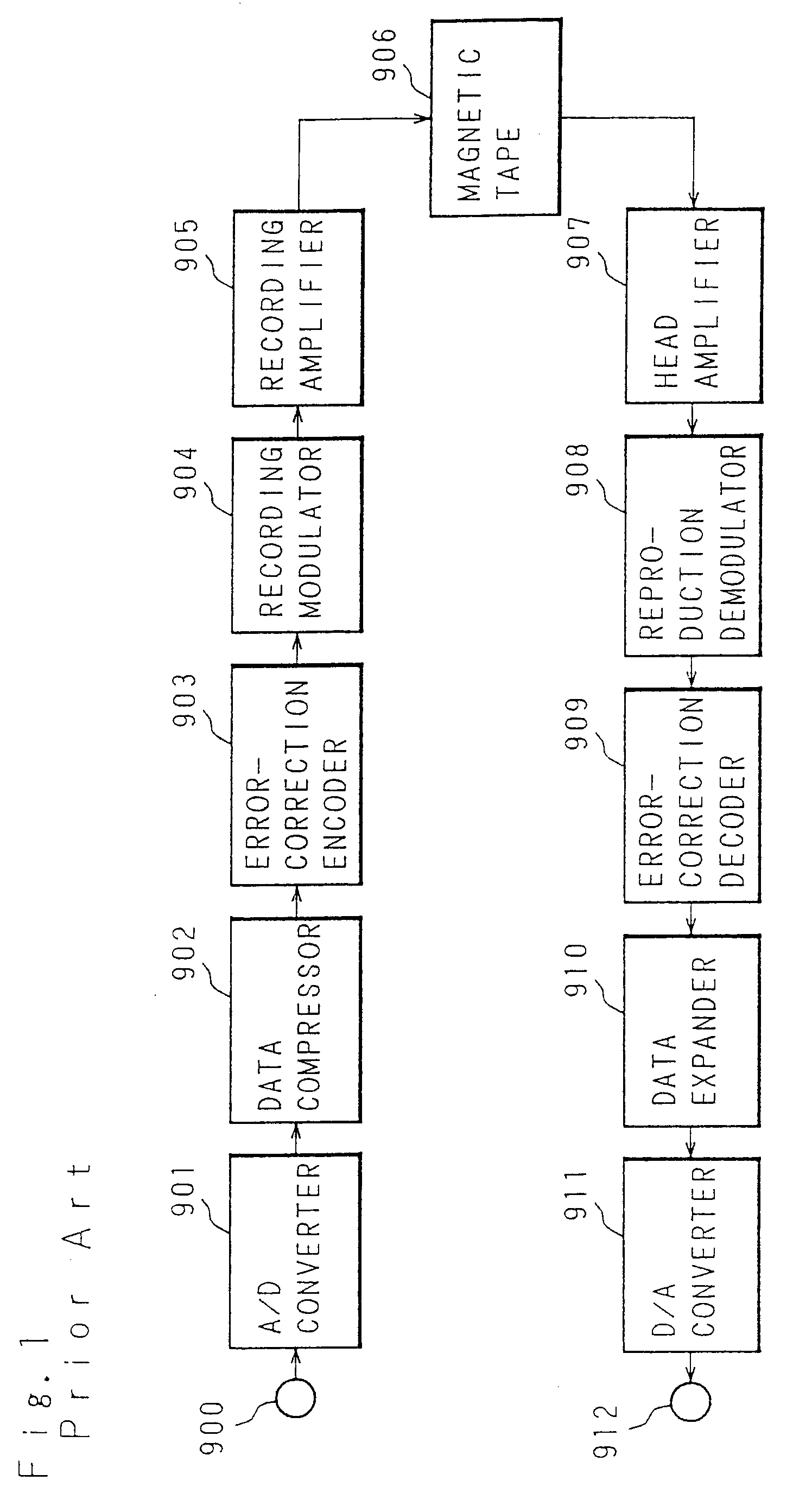
[0107] Hereinafter, a first embodiment of the present invention will be described with reference to the drawings. FIG. 25 is a block diagram illustrating the first embodiment of the invention. In FIG. 25, 1 designates an input terminal for a digital video signal, 2 designates a blocking circuit, which forms into a block a digital video signal input through the digital video signal input signal terminal 1, 30 designates a motion-compensation predicting circuit which performs motion-compensation prediction between the block output from the blocking circuit 2 and an intra-field and outputs a difference signal between an input block and a prediction block, 31 designates a determiner which selects the one having the smaller sum of absolute values between the input signal from the blocking circuit 2 and a prediction difference signal from the motion-compensation predicting circuit 30, 32 designates a first switch which selectively outputs encoded blocks output from the blocking circuit 2 ...
embodiment 2
[0113] According to Embodiment 1 described above, in the determiner 31, the output having the smaller sum of absolute values is selected from the outputs of the blocking circuit 2 and motion-compensation predicting circuit 30, to be output to the first switch 32. In a field where determiner 31 selects the forced intra mode more frequently than the prediction mode, it may be judged that a scene change has occurred in the field, and assuming that the whole field is in the intra mode encoding may be performed. An embodiment constructed so as to perform this operation is Embodiment 2 described below.
[0114]FIG. 27 is a block diagram showing the configuration of the second embodiment. In the figure, 40 designates a determiner which selects the one having the smaller sum of absolute values, from an input block from the blocking circuit 2 and a prediction difference block from the motion-compensation predicting circuit 30, and which judges a field where the input block from the blocking ci...
embodiment 3
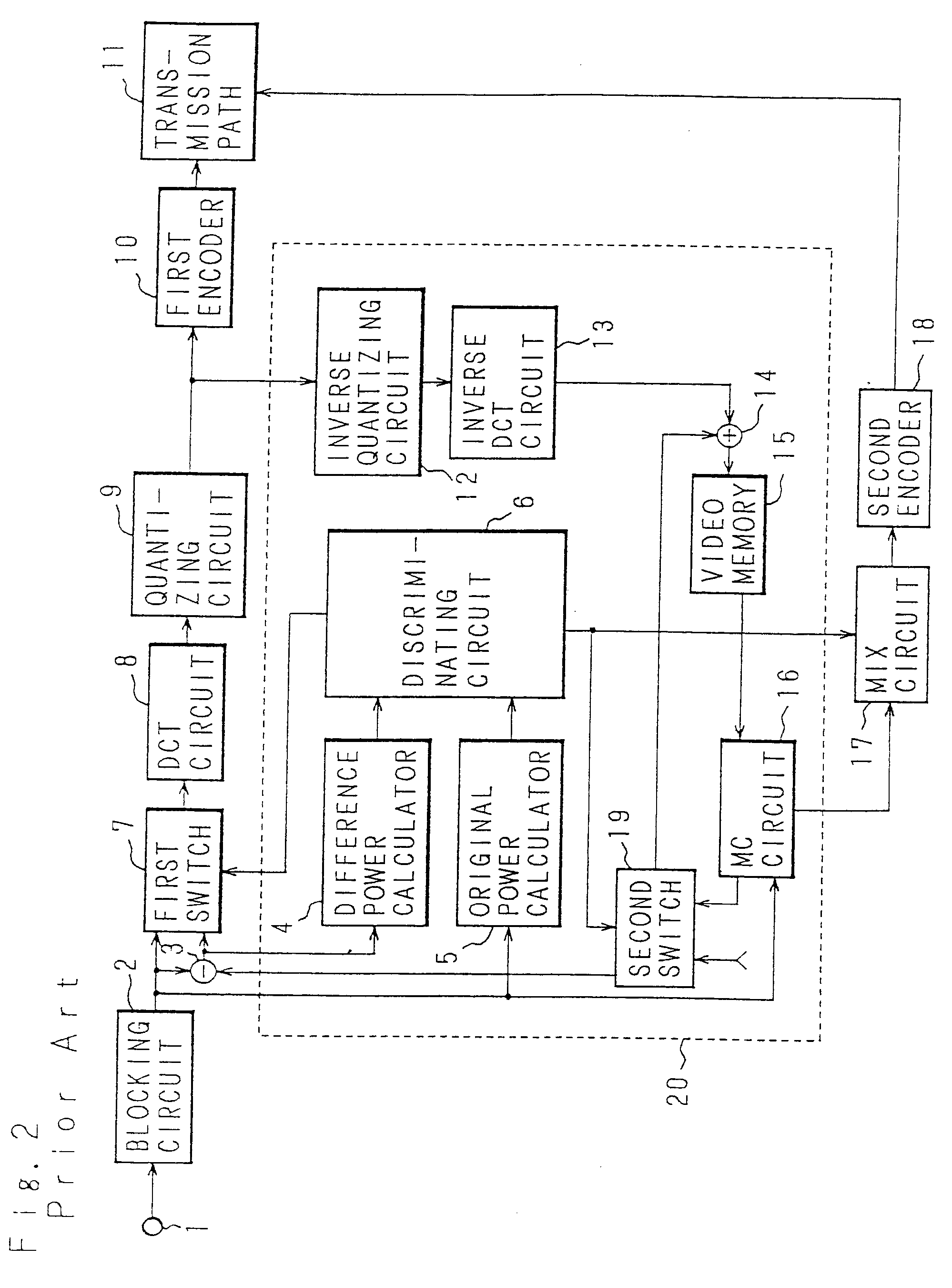
[0120]FIG. 31 is a block diagram showing the configuration of a high-efficiency encoder in Embodiment 3. In FIG. 31, 1-14 and 16-20 designate the elements identical to those of the conventional apparatus in FIG. 2. The reference numeral 50 designates a mode counter which counts the number of blocks of the intra mode, 51 designates a direction switching circuit which compares a predetermined number of blocks with the number of blocks of the intra mode output from the mode counter and which determines the reference picture for the next field, and 52 designates a video memory which stores output blocks in order to perform motion-compensation prediction and which outputs the reference picture for the next field as the search range.
[0121] Then, the operation will be described. Irrespective of an intra-field or a prediction-field, input digital video signals are by the blocking circuit 2 segmented into input blocks a unit of which consists of m [pixels]×n [lines]. In order to obtain a di...
PUM
| Property | Measurement | Unit |
|---|---|---|
| frequency multiplex recording | aaaaa | aaaaa |
| frequency multiplex recording | aaaaa | aaaaa |
| width | aaaaa | aaaaa |
Abstract
Description
Claims
Application Information