Horizontal articulated robot
- Summary
- Abstract
- Description
- Claims
- Application Information
AI Technical Summary
Benefits of technology
Problems solved by technology
Method used
Image
Examples
embodiment 1
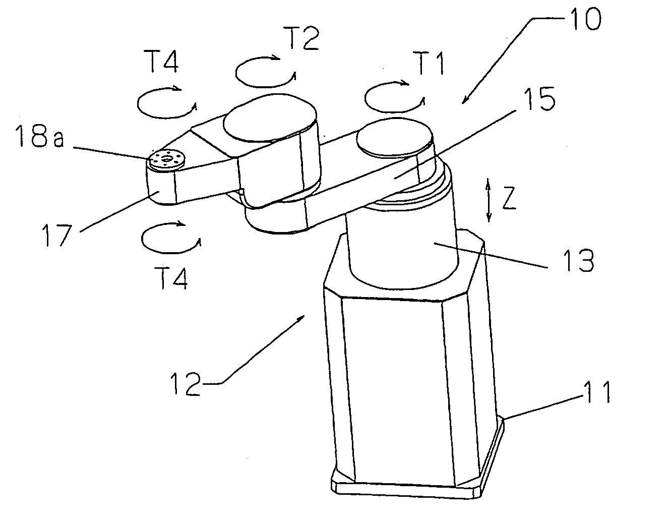
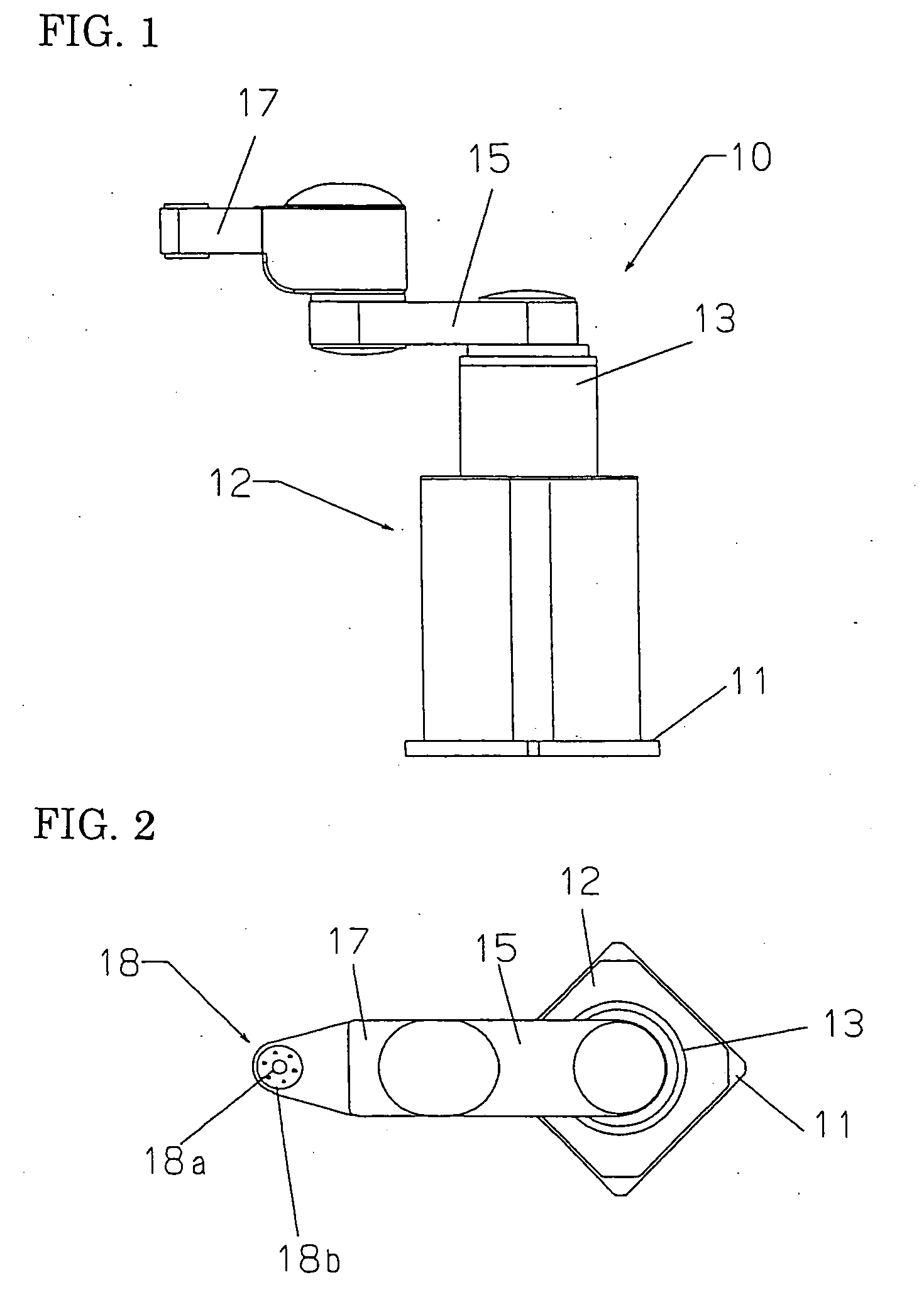
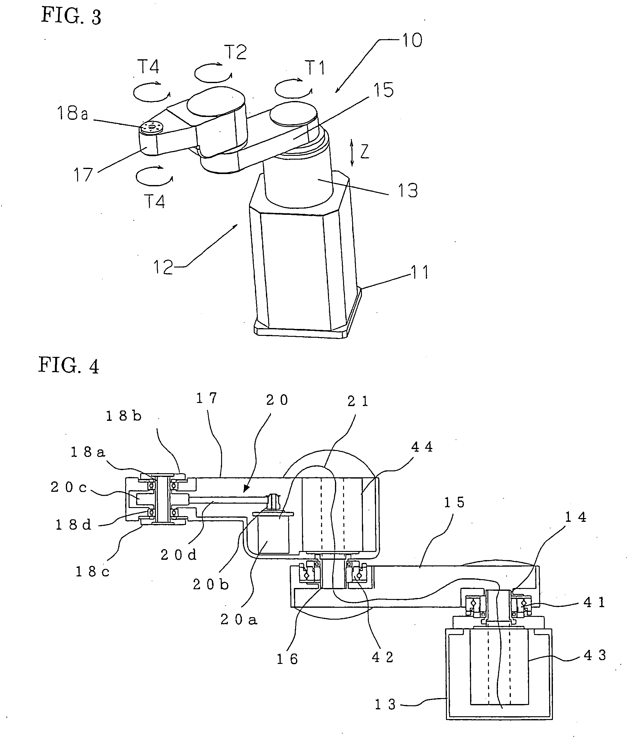
[0038]FIG. 1 is a side elevational view of a horizontal articulated robot of an embodiment 1 according to the present invention, FIG. 2 is an upper surface view of the horizontal articulated robot, and FIG. 3 is a perspective view of the horizontal articulated robot. Further, FIG. 4 is a sectional view showing an arm portion of the horizontal articulated robot.
[0039] The horizontal articulated robot 10 includes a base 11, an arm base 13 coupled with the base 11 through an up / down movement mechanism 12, a first arm 15 coupled with the arm base 13 through a first joint shaft 14, a second arm 17 coupled with the first arm 15 through a second joint shaft 16, and a working shaft 18 rotatably disposed to the extreme end of the second arm 17.
[0040] The first and second arms 15 and 17 are horizontal arms that turn in a horizontal surface, and the second arm 17 constitutes an extreme end arm. Further, the number of the arms is not particularly limited and ordinarily set between 2 and 4.
[0...
embodiment 2
[0056]FIG. 8 is a sectional view of the portion of a second arm 17 in a horizontal articulated robot of an embodiment 2 according to the present invention.
[0057] Although the embodiment 1 described above shows the hollow mounting flanges 18b, 18c disposed to both the upper and lower ends of the hollow rotary shaft 18a, the embodiment 2 shows a hollow rotary shaft 18e having a hollow mounting flange disposed on one side, for example, an upper hollow mounting flange 18b. Further, the lower portion of the hollow rotary shaft 18e extends somewhat long toward the lower side of the second arm 17. A required assembly job can be executed by mounting a not shown tool (for example, screwdriver, welding torch, and the like) on the projecting portion extending downward.
embodiment 3
[0058]FIG. 9 is a configurational view of a coupling means which couples a hollow rotary shaft 18a with an end effector 25 and shows an embodiment 3 according to the present invention, wherein (A) is a sectional view of a coupling state, (B) is a lower surface view on a hollow rotary shaft side, and (C) is an upper surface view on a coupling means side.
[0059] Although the hollow rotary shaft 18a is coupled with the end effector by the flange coupling in the embodiments 1 and 2 described above, the embodiment 3 is arranged such that they can be coupled with each other by screw coupling in an instant mounting / dismounting system.
[0060] More specifically, a coupling 33, which has a female screw 32 cut thereto, is disposed to a hollow cylinder 31 having an end effector 25 previously mounted on the lower end thereof. Further, the hollow cylinder 31 has a positioning key 34 disposed thereto. A coupling means on the end effector 25 side is arranged by the arrangement described above.
[006...
PUM
 Abstract
Description
Claims
Application Information
 - R&D
- Intellectual Property
- Life Sciences
- Materials
- Tech Scout
- Unparalleled Data Quality
- Higher Quality Content
- 60% Fewer Hallucinations
Browse by: Latest US Patents, China's latest patents, Technical Efficacy Thesaurus, Application Domain, Technology Topic, Popular Technical Reports.
© 2025 PatSnap. All rights reserved.Legal|Privacy policy|Modern Slavery Act Transparency Statement|Sitemap|About US| Contact US: help@patsnap.com


