Bipolar plate for a fuel cell

a technology of bipolar plates and fuel cells, applied in the field of distribution plates, can solve the problems of high fuel cell operating cost, degrading the overall efficiency of the fuel cell and its lifetime, and reducing the active distribution area of the plate, so as to reduce the active distribution area

Active Publication Date: 2006-06-22
SN DETUDE & DE CONSTR DE MOTEURS DAVIATION S N E C M A
View PDF3 Cites 31 Cited by
  • Summary
  • Abstract
  • Description
  • Claims
  • Application Information

AI Technical Summary

Benefits of technology

[0007] An object of the present invention is to provide a bipolar plate design for a fuel cell that enables the reagent species (fuel / oxidizer) to be distributed in sufficient and uniform manner when using a mixture of gases that contains only a fraction of the reagent gas, and to do so without reducing the active distribution area of the plate.
[0009] Thus, with the bipolar plate design of the invention, it is possible to have bipolar plates with a larger number of channels compared with conventional bipolar plates. By increasing the number of channels formed in the outside face of each half-plate, the length of the path to be followed by the reagent gas flow is reduced correspondingly. These channels can be reduced down to the length corresponding to the distance between the two grooves (the most direct path). It is then possible to adapt the length of the distribution channels to the reagent content of the gaseous mixture used. With such bipolar plates, it is no longer essential to make use of flows having a high concentration of reagent or to increase gas flow rates.
[0010] In addition, in the bipolar plate of the invention, the feed and exhaust grooves for the distribution channels, which must be relatively wide in order to conserve a section of sufficient size in spite of the small thickness of the half-plate, are formed in the inside faces of the half-plates. This avoids any risk of losing support for the membrane on which the outside faces of the half-plates come to bear.
[0012] With plates of relatively long length, at least one of the first and second grooves may present a shape in the form of two oppositely-directed triangles meeting via their narrow ends in the middle of the plate, the opposite ends of the two triangles forming two distinct feed inlets for the groove. This enables two inlets to be provided for a single groove and thus enables a larger quantity of fluid to be introduced therein.
[0017] The two half-plates constituting the bipolar plate of the invention may be identical, thereby further rationalizing manufacturing costs, or else they may be different in order to be adapted to distributing two fluids at different concentrations.

Problems solved by technology

The use of pure reagent leads to a high operating cost for the fuel cell and poses problems of storage for the reagents, in particular for the hydrogen.
Consequently, with the above-described bipolar plates designed for pure reagents, it is not possible to provide a uniform distribution of the reagent species over the entire working area of the membrane, thereby degrading the overall efficiency of the fuel cell and its lifetime.

Method used


Image

  • Bipolar plate for a fuel cell
  • Bipolar plate for a fuel cell
  • Bipolar plate for a fuel cell

Examples


Embodiment Construction

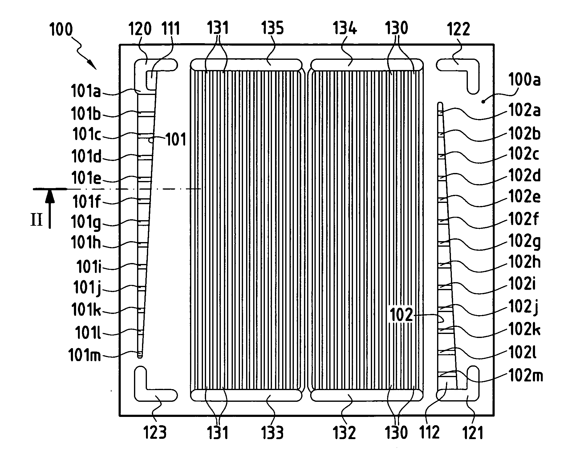
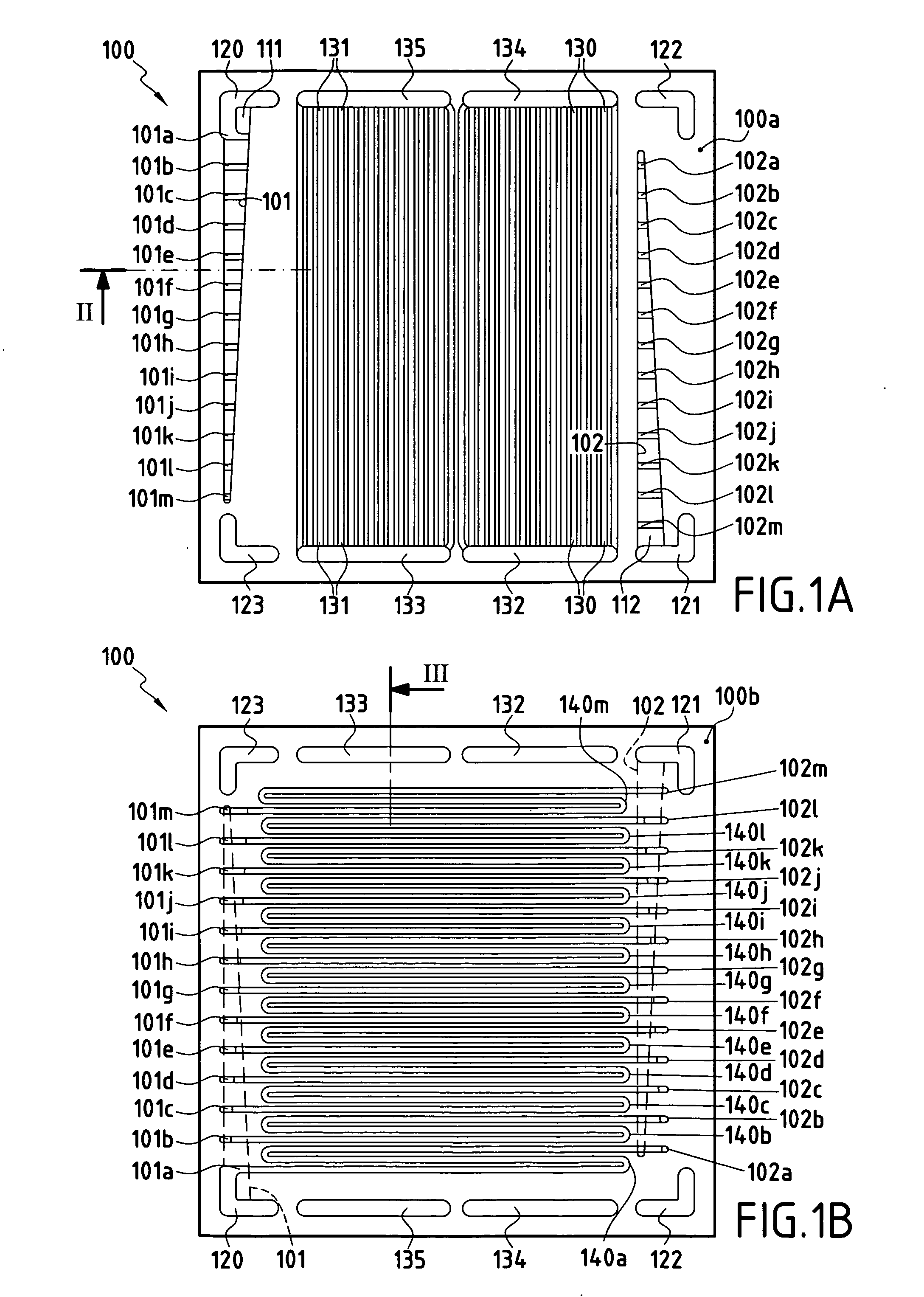
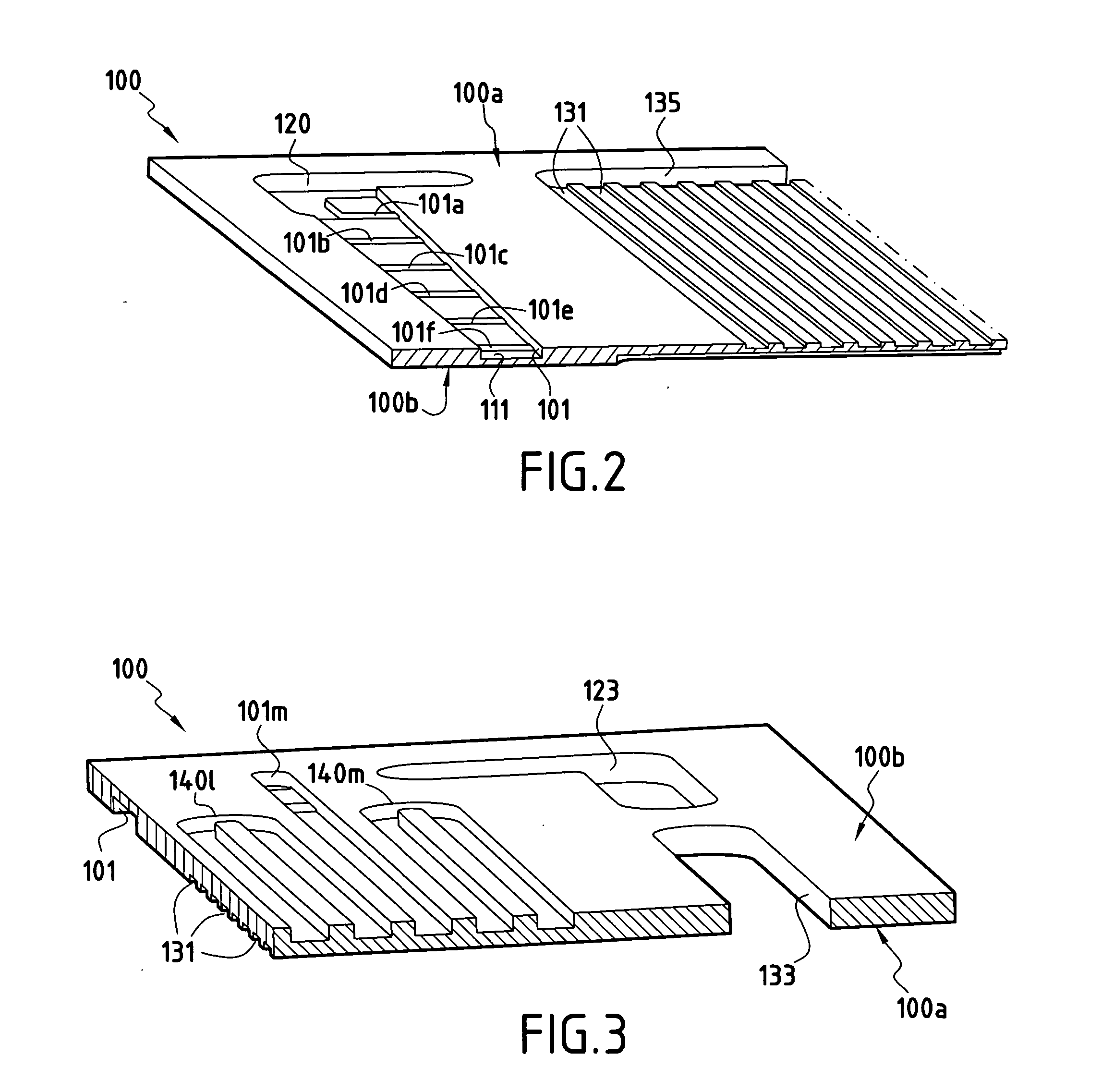
[0028] The present invention provides a design for a bipolar plate that enables reagent gas to be distributed uniformly, particularly when using a mixture of gases that comprises only a fraction of the reagent gas, as is the case for example when using air (oxygen source) or when using a reformate gas (hydrogen source). To compensate for the depletion in reagent of a gas mixture compared with a pure reagent gas, the invention proposes bipolar plates having distribution channels in larger numbers than in prior art bipolar plates. Channel length can thus be shortened in proportion to the number of channels provided on the bipolar plate. By reducing channel length, the distance to be traveled by the gaseous mixture is shortened, and consequently the depletion of the mixture in reagent prior to leaving the channels is reduced. The length of each channel is determined as a function of the concentration of reagent present in the gas mixture used, i.e. this length is determined so that the...


PUM

PropertyMeasurementUnit
lengthaaaaaaaaaa
thicknessaaaaaaaaaa
shapesaaaaaaaaaa

Abstract

The invention relates to a bipolar plate for a fuel cell, the plate being made up of two half-plates assembled one against the other via their inside faces, each half-plate including in its inside face at least a first groove and a second groove that are spaced apart from each other. The bottoms of said grooves each presenting a plurality of orifices distributed along each groove and opening out into the outside face of the half-plate. The outside face of each half-plate includes a plurality of distribution channels, each distribution channel connecting a respective orifice of the first groove to a respective orifice of the second groove.

Description

FIELD OF THE INVENTION [0001] The present invention relates to fuel cells and more particularly to distributor plates known as “bipolar plates” that serve to feed the electrodes of the fuel cell with reagent. BACKGROUND OF THE INVENTION [0002] A fuel cell typically comprises a set of individual cells each constituted by two electrodes (anode and cathode) separated by a member acting as an electrolyte and assembled to one another in series so as to form a stack. By feeding each electrode with suitable reagent, i.e. fuel for one of the electrodes and oxidizer for the other, an electrochemical reaction is obtained that enables a potential difference to be created between the electrodes, and thus enables electricity to be produced. The stack corresponds to the core of the fuel cell, since it is within the stack that the electrochemical reaction takes place that enables electricity to be generated. [0003] In order to feed each electrode with reagent, specific interface elements are used ...

Claims


Application Information

Patent Timeline
Patent Type & Authority Applications(United States)
IPC IPC(8): H01M8/02H01M8/10H01M2/08B32B3/30
CPCH01M8/0206H01M8/0247H01M8/0258Y10T428/24537H01M8/0297Y02E60/50H01M8/0267H01M8/2483H01M8/0263H01M8/026H01M8/02H01M8/0276
Inventor GARCEAU, PATRICK
Owner SN DETUDE & DE CONSTR DE MOTEURS DAVIATION S N E C M A
Why Eureka
Try Eureka