
Communication apparatus, control method of communication apparatus, and control program of communication apparatus

Inactive Publication Date: 2006-06-22
CANON KK
View PDF100 Cites 62 Cited by
  • Summary
  • Abstract
  • Description
  • Claims
  • Application Information

AI Technical Summary

Benefits of technology

[0014] An object of the present invention is to solve the above conventional problems. In other words, the present invention aims to provide a communication apparatus corresponding to a voice-band analog communication path and a network communication path, wherein high-speed and high-reliability data communication can be performed by selecting the appropriate communication path without any complicated user's operation.

Problems solved by technology

Here, in an analog facsimile procedure, although any problem does not occur when binary (i.e., black and white) image data or the like is transmitted, a problem that a long communication time is necessary occurs when large-capacity color image data (according to a JPEG (Joint Photographic Experts Group) format or the like) obtained by means of a digital camera or the like is transmitted.
However, in that case, there is a problem that the communication partner terminal (i.e., a reception side) has to take the trouble to access the server for receiving the image data, and there is also a problem that real-time communication cannot be performed.
In other words, it is difficult in that case to achieve data communication by a simple operation as in the conventional facsimile machine of only setting a mere communication partner's telephone number.
That is, it is impossible to easily perform image transmission only by inputting a destination's telephone number as in the conventional facsimile machine.

Method used


Image

  • Communication apparatus, control method of communication apparatus, and control program of communication apparatus
  • Communication apparatus, control method of communication apparatus, and control program of communication apparatus
  • Communication apparatus, control method of communication apparatus, and control program of communication apparatus

Examples


first embodiment

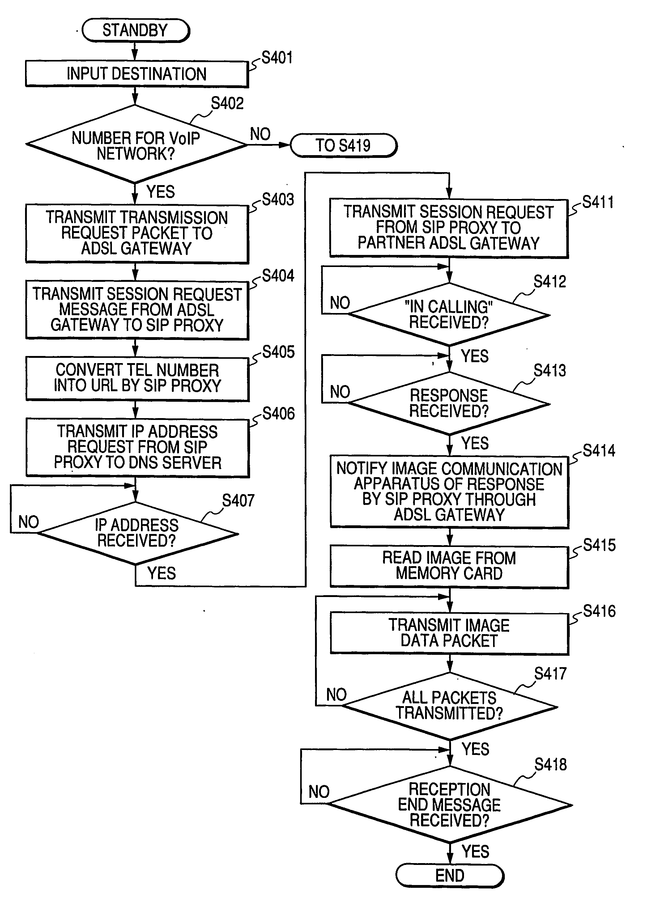
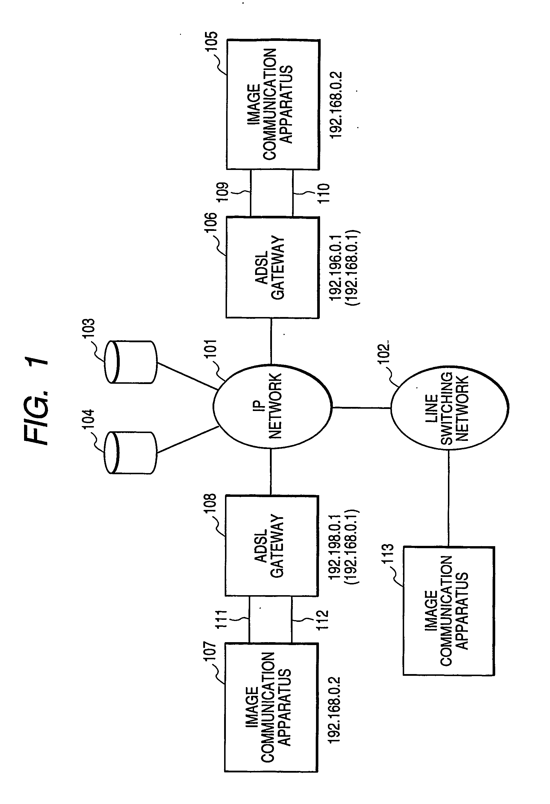
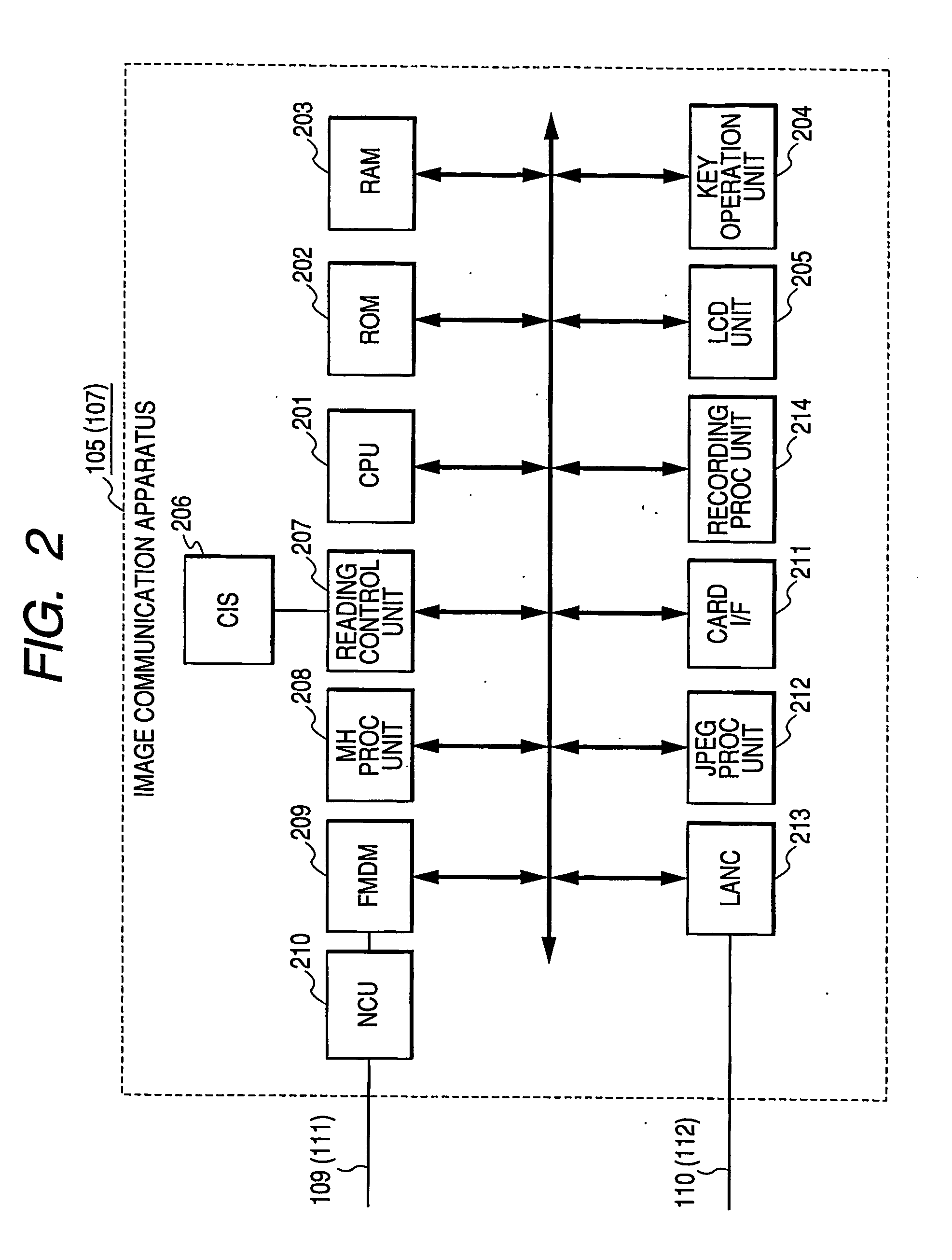
[0036]FIG. 1 is a block diagram showing the structure of a network system to which the present embodiment is applicable. In FIG. 1, numeral 101 denotes an IP network, numeral 102 denotes a line switching network, numeral 103 denotes an SIP proxy (or SIP proxy server) for VoIP, numeral 104 denotes a DNS server (i.e., domain name server), numeral 105 denotes a first image communication apparatus (private IP address=192.168.0.2), numeral 106 denotes an ADSL gateway (global IP address=192.196.0.1: private IP address=192.168.0.1), numeral 107 denotes a second image communication apparatus (private IP address=192.168.0.2), and numeral 108 denotes an ADSL gateway (global IP address=192.198.0.1: private IP address=192.168.0.1). Likewise, numerals 109 and 111 denote analog telephone interfaces respectively, numerals 110 and 112 denote CSMA / CD interfaces respectively, and numeral 113 denotes a third image communication apparatus. Incidentally, although, in the following, the component parts 1...

second embodiment

[0105] In the above-described first embodiment, the structure that the NCU 210 acting as the interface for the line switching network is provided in the image communication apparatus is explained by way of example. In the meantime, in, the second embodiment, the structure that the NCU 210 is not used as the interface for the line switching network will be explained by way of example.

[0106] In the present embodiment, to a communication partner's image communication apparatus capable of using an IP protocol, image data is transmitted, without using the facsimile protocol as in the first embodiment, by using a data transmission / reception protocol on the IP network. Moreover, to a communication partner's image communication apparatus incapable of using the IP protocol (e.g., an image communication apparatus not connected to the VoIP network but connected only to the general line switching network), image data transmission is performed by transmitting a facsimile signal as a voice signa...

third embodiment

[0200] In the above-described second embodiment, the image communication apparatuses 105 and 107 each of which does not has any NCU is explained.

[0201] In the third embodiment, it is further considered how to lower costs for the image communication apparatuses 105 and 107.

[0202] In the present embodiment, each of the image communication apparatuses 105 and 107 has the same structure as shown in FIG. 11 except for the FMDM 209, and the same parts as those in the second embodiment will be refrained from being explained.

[0203] The present embodiment is different from the second embodiment in the communication portion through the gateway 1111. Hereafter, it should be noted that the present embodiment will be explained with reference to the image communication apparatus device 105 as a representative.

[0204] That is, in the present embodiment, the image communication apparatus 105 communicates with the image communication apparatus 113 on the communication partner side according to th...


PUM


Abstract

In a communication apparatus corresponding to a voice-band analog communication path and a network communication path, high-speed and high-reliability data communication is achieved by selecting the appropriate communication path without any complicated user operation. The communication apparatus which performs IP communication and analog communication through an ADSL gateway obtains a communication partner IP address from an SIP proxy when a communication partner telephone number corresponds to a VoIP network, and transmits / receives communication data to / from the communication partner on an IP network based on a file transmission / reception protocol such as FTP, HTTP, or the like. The communication apparatus performs analog facsimile communication on a line switching network when the communication partner telephone number does not correspond to the VoIP network, and performs the analog facsimile communication when the communication partner corresponds to the VoIP network but does not have any digital communication means.

Description

TECHNICAL FIELD [0001] The present invention relates to a communication apparatus which has an IP (Internet Protocol) communication means and transmits / receives communication data to / from a communication partner station identified by a telephone number, a control method of the communication apparatus, and a control program for the communication apparatus. BACKGROUND ART [0002] In recent years, a broadband communication line such as the ADSL (Asymmetric Digital Subscriber Line) or the like capable of performing high-speed data transmission is in widespread use. Here, the ADSL is characterized by using the same metallic cable as the existing subscriber's line, whereby the identical line can be used for both an analog telephone service and a network connection service. That is, it is possible by inserting a frequency division filter called a splitter between the communication line and a communication terminal to separate the line for transmitting a voice band signal and the line for tr...

Claims


Application Information

Patent Timeline
IPC IPC(8): G06F15/16G06FH04L12/28H04L29/06H04L29/08H04M11/00H04N1/00H04N1/32
CPCH04L12/5692H04L29/06027H04L65/1006H04N1/0022H04L67/06H04N1/00214H04L65/1104H04L69/085H04L65/1101H04L69/08H04N1/001H04N1/32721H04N1/3278
Inventor IZUMI, MICHIHIRO
Owner CANON KK
Learn More