Convective cushion with positive coefficient of resistance heating mode

a cushioning and coefficient technology, applied in the field of temperature controlled mattress pads, can solve the problems of short circuit, drop in heating efficiency, and longer heating time to reach an adequate level, and achieve the effects of reducing mechanical stress, facilitating wireless communication, and reducing short circui

Inactive Publication Date: 2006-06-29
FEHER STEVE
View PDF8 Cites 124 Cited by
  • Summary
  • Abstract
  • Description
  • Claims
  • Application Information

AI Technical Summary

Benefits of technology

[0017] The heating module preferably includes a PTC type heating element in conduction with a base plate and a number of heat exchanger fins. Preferably the heating element is sandwiched between a pair of the base plates and the heat exchanger fins, and there is a seal between the base plates to minimize air flow from the blower from passing there between. A remote control for the user's convenience may be provided and a foldable antenna attachable to the convective unit facilitates wireless communication between the remote control and controller unit, although corded remote control may also be utilized or the controls located on the power unit itself. The power unit may include multiple PTC elements including of varying capability to allow the user to more precisely control the output temperature of the air, and may include a speed control for the blower.
[0018] The user resting atop the cushion is able to control the blower and heating module to deliver air of a desired temperatur

Problems solved by technology

This suffers from certain disadvantages, however, including that the electrical conductors are located within the cushion itself.
Over time, the wires, carbon fiber strips or the like being subject to repeated weight loads and mechanical stresses may become physically damaged causing sparks from short circuits, and an occasional fire.
The disadvantage here is that it takes longer to reach an adequate heating level, because of the drop in heating efficiency caused by the insulati

Method used


Image

  • Convective cushion with positive coefficient of resistance heating mode
  • Convective cushion with positive coefficient of resistance heating mode
  • Convective cushion with positive coefficient of resistance heating mode

Examples


Embodiment Construction

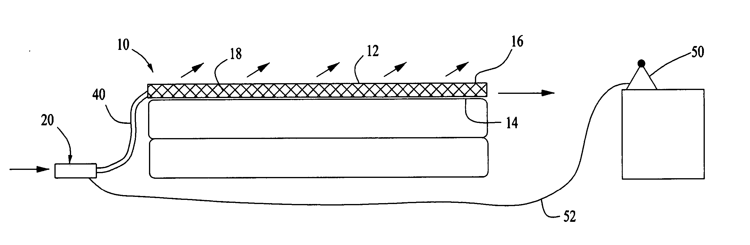
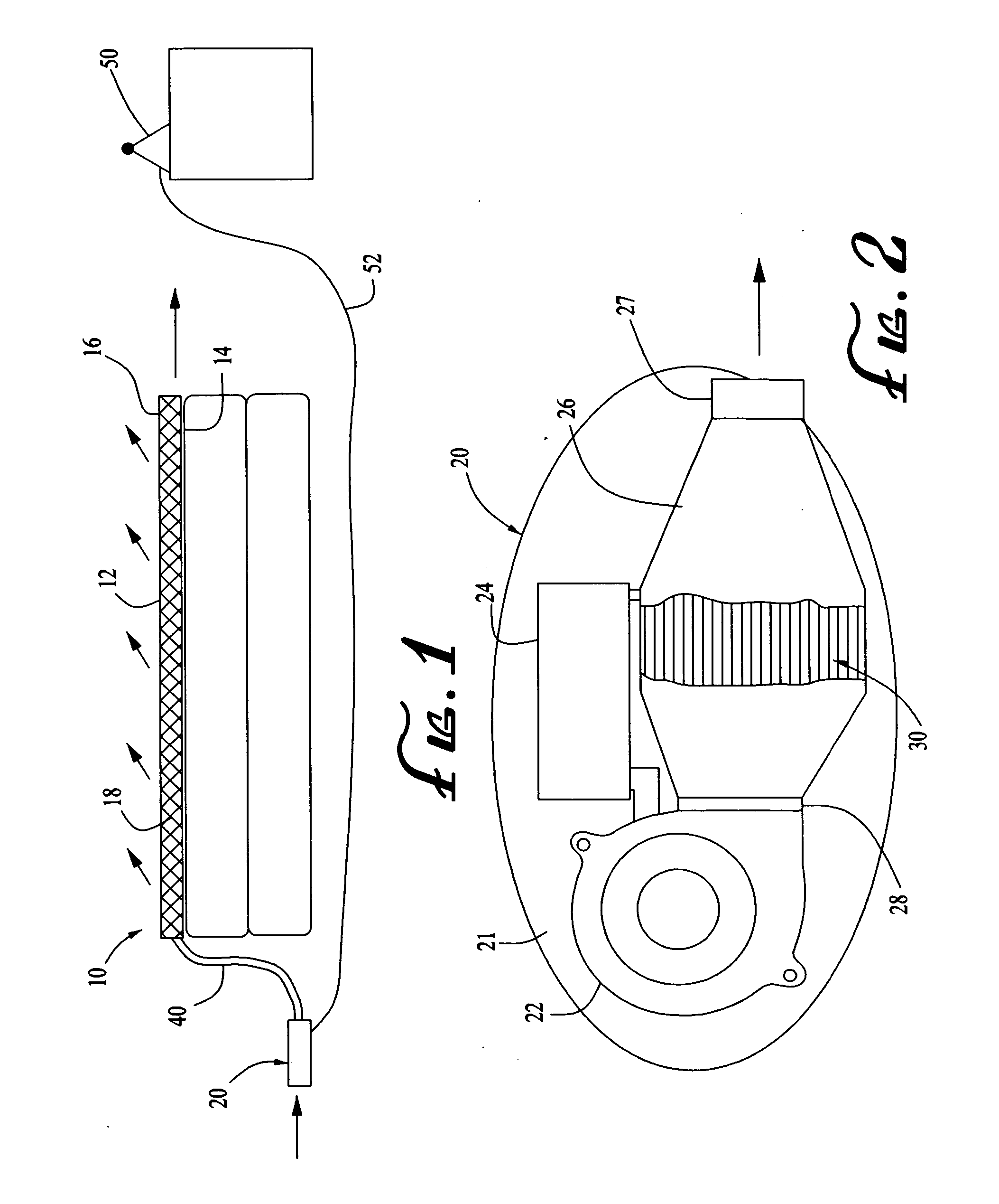
[0071] Initially referring to FIG. 1, shown is the convective cushion 10 placed upon a conventional mattress, including a plenum 12 constructed of a bottom surface 14 secured around its perimeter to a top surface 16. The bottom surface 14 is preferably air impervious, although placement on a conventional mattress may render an air permeable surface largely impervious. The top surface 16 is air-permeable although sufficiently impervious that a greater air pressure can be maintained inside the enclosed space.

[0072] Inside the plenum 12 is tubular spacer material 18 or equivalent. U.S. Pat. Nos. 6,085,369 and 6,263,530 pioneered the use of such tubular spacer fabric 18 as an air flow structure for seats, mattresses, mattress pads, and other articles of furniture that can be sat on or laid down upon. Although the preferred embodiment of this invention utilizes the same tubular spacer fabric 18 as described in the issued Feher '369 and '530 patents, it is possible to utilize other air f...


PUM


Abstract

A cushion that is heated convectively using a positive coefficient of resistance type resistive heating element that is provided with heat exchanging surfaces, includes a mattress pad, seat or the like with a bottom surface secured around its perimeter to an air permeable top surface, forming a plenum and containing tubular spacer material therein. The plenum is connected to a power unit housing a blower, a heating module and a controller unit. The heating module preferably includes a PTC type heating element in conduction with a base plate and a number of heat exchanger fins. Preferably the heating element is sandwiched between a pair of the base plates and the heat exchanger fins, and there is a seal between the base plates to minimize air flow from the blower from passing there between. A remote control for the user's convenience may be provided, and a foldable antenna attachable to the convective unit facilitates wireless communication between the remote control and controller unit. The user resting atop the cushion is able to control the blower and heating module to deliver air of a desired temperature and quantity to the cushion and through the top surface. The invention advantageously replaces the current carrying, conductive wires and insulation found inside prior art heated mattresses, enhancing safety and performance while at the same time offering a cooled or ventilated capability.

Description

CROSS REFERENCE TO RELATED DOCUMENTS [0001] This application is continuation-in-part of utility patent application Ser. No. 11 / 024,073 (filed Dec. 27, 2004) entitled “Variable Temperature Cushion And Heat Pump.”BACKGROUND OF THE INVENTION [0002] 1. Field of the Invention [0003] The present invention relates to temperature controlled mattress pads, seats or other cushions, and more particularly to such a cushion that is heated by a positive temperature coefficient (PTC) element and ventilated as well. [0004] 2. Description of the Related Art [0005] Resistance wires oftentimes with PTC resistive elements are the conventional way of heating a cushion by conduction. This suffers from certain disadvantages, however, including that the electrical conductors are located within the cushion itself. Over time, the wires, carbon fiber strips or the like being subject to repeated weight loads and mechanical stresses may become physically damaged causing sparks from short circuits, and an occasi...

Claims


Application Information

Patent Timeline
IPC IPC(8): H05B3/00A47C27/08H05B1/00
CPCA47C7/74A47C7/742A47C7/748A47C21/044A47C21/048A47C27/008A47C27/082A47C31/006B60N2/5635B60N2/5657Y10S5/941
Inventor FEHER, STEVE
Owner FEHER STEVE
Why Eureka
Try Eureka