Fan driven emergency generator

Inactive Publication Date: 2006-06-29
PRATT & WHITNEY CANADA CORP
View PDF32 Cites 118 Cited by
  • Summary
  • Abstract
  • Description
  • Claims
  • Application Information

AI Technical Summary

Benefits of technology

[0006] In another aspect, the present invention provides an emergency electrical power generating apparatus for use with an aircraft gas turbine engine having a fan assembly, which comprises an

Problems solved by technology

It can present significant challenges in aircraft design to find a suitable location for the RAT and to design a deployment system to position on the RA

Method used


Image

  • Fan driven emergency generator
  • Fan driven emergency generator
  • Fan driven emergency generator

Examples


Embodiment Construction

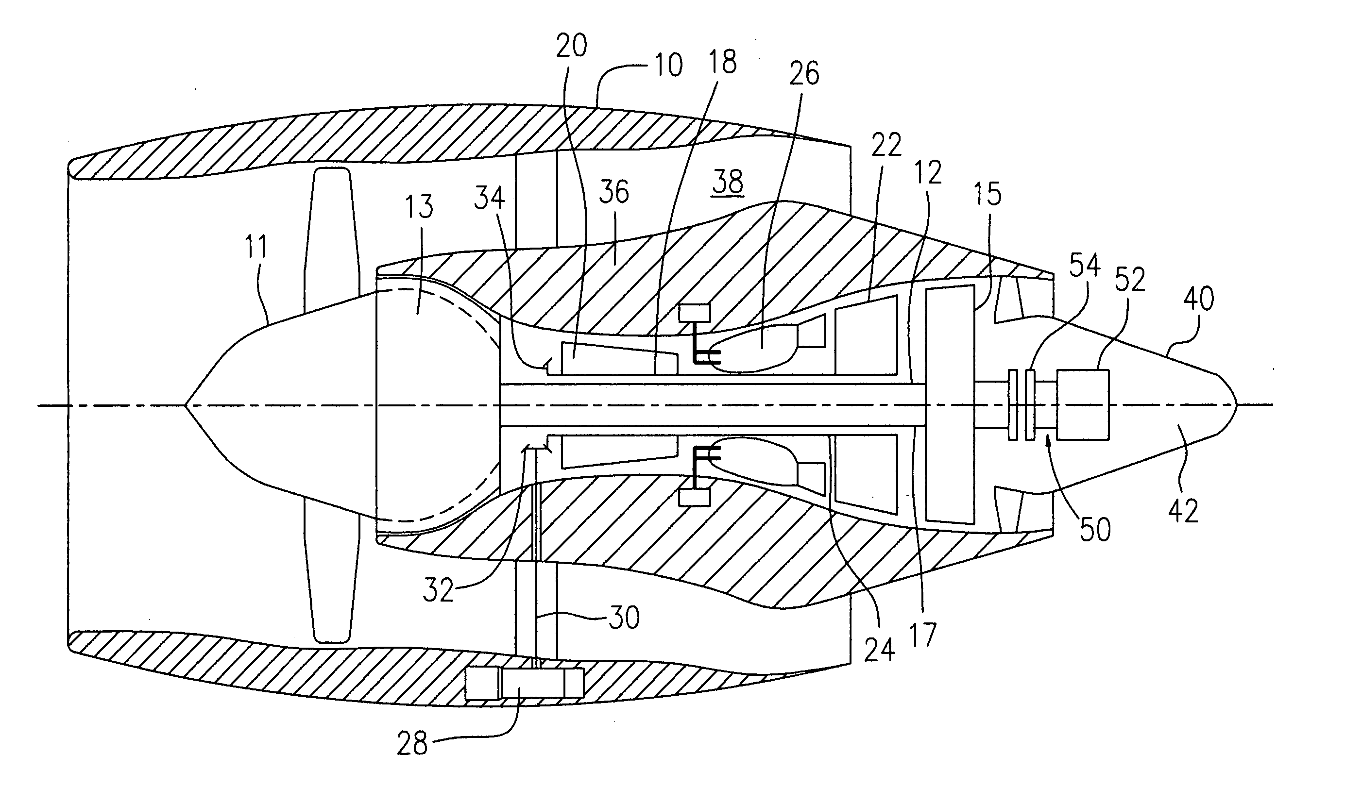
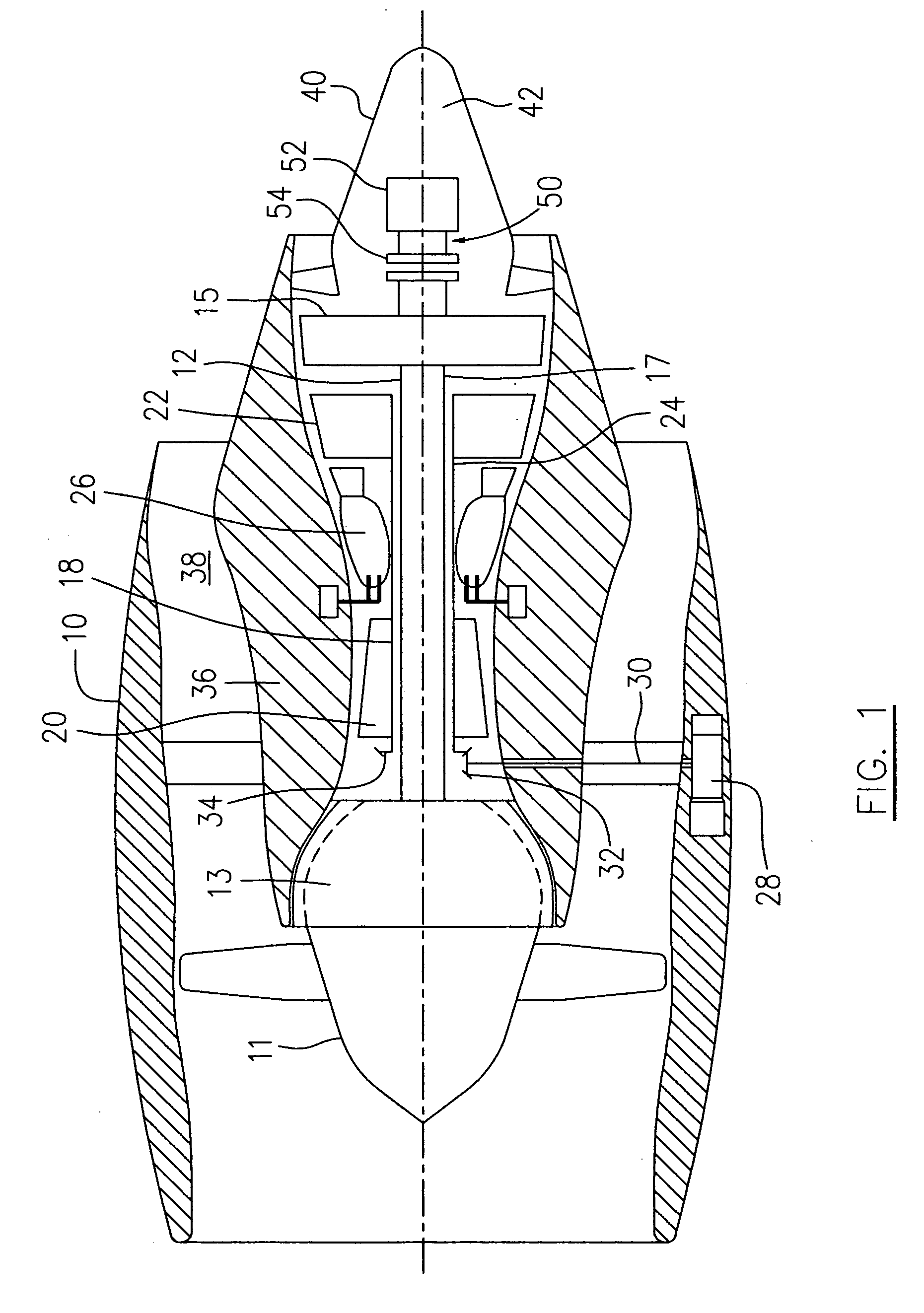
[0015]FIG. 1 schematically illustrates a turbofan engine which incorporates an embodiment of the present invention to illustrate, as an example, the application of the present invention. The turbofan engine of FIG. 1 includes a housing or nacelle 10, a low pressure spool assembly seen generally at 12 which includes a fan assembly 11, low pressure compressor 13, low pressure turbine 15 and low pressure spool shaft 17 connecting the low pressure compressor 13 with the low pressure turbine 15, a high pressure spool assembly seen generally at 18 which includes a high pressure compressor 20, high pressure turbine 22 and high pressure spool shaft 24 connecting the high pressure compressor 20 with the high pressure turbine 22. The engine further comprises a burner seen generally at 26 and an accessory drive assembly seen generally at 28 which is coupled to the high pressure spool shaft 24 through a tower shaft 30 and a pair of bevel gears 32, 34.

[0016] An engine core casing 36 is provided...


PUM


Abstract

An emergency electrical power generating apparatus for use with a turbofan engine comprises an electrical generator and a clutch assembly. The clutch connects the generator with a fan assembly of the engine only during a windmill action of the fan assembly.

Description

TECHNICAL FIELD [0001] The invention relates generally to an aircraft generator and, more particularly, to an improved emergency electrical power generating apparatus for use with an aircraft gas turbine engine having a fan assembly. BACKGROUND OF THE ART [0002] In modern turbofan powered aircraft, an emergency power source is required for control of flight surfaces in the event of total loss of the availability of the primary power sources, i.e. engine driven hydraulic pumps and / or engine driven electrical generators. In small airplanes this power is provided by the energy stored in aircraft batteries. In larger airplanes, a single ram air turbine, or RAT with an integral generator or hydraulic pump is provided for deployment in emergency situations only. The emergency power source is the aircraft's own air speed (kinetic energy) and altitude (potential energy). However, a RAT must be positioned away from the aircraft surfaces and is usually mounted under the wing or below the nose...

Claims


Application Information

Patent Timeline
IPC IPC(8): F02C7/32
CPCB64D41/007F02C7/32H02K7/1823Y02E10/721F05D2220/326F05D2220/34F05D2220/36F05D2220/76Y02E10/72
Inventor WELCH, RICHARDALBERO, JOSEBUECHE, GERARDDEGROFF, WILLIAMMAKUSZEWSKI, JERZY
Owner PRATT & WHITNEY CANADA CORP
Why Eureka
Try Eureka