Plasma generating apparatus, plasma generating method and remote plasma processing apparatus

a plasma generating apparatus and plasma technology, applied in the direction of electric discharge tubes, chemical vapor deposition coatings, coatings, etc., can solve the problems of increasing the risk of coolant tube breakage, the gas excitation portion cannot be sufficiently cooled down, and the plasma excitation efficiency is difficult to achieve, etc., to achieve the effect of improving plasma excitation efficiency, microwave transmission and radiation efficiency, and reducing the size of the plasma generating apparatus

Inactive Publication Date: 2006-06-29
TOKYO ELECTRON LTD
View PDF15 Cites 110 Cited by
  • Summary
  • Abstract
  • Description
  • Claims
  • Application Information

AI Technical Summary

Benefits of technology

The present invention is a plasma generating apparatus that improves plasma excitation efficiency by using high microwave transmission and radiation efficiencies. The microwaves radiated from the resonator pass through without any interruption to excite a process gas within the whole interior space of the chamber. This reduces the size of the plasma generating apparatus and the amount of process gas needed, resulting in cost savings. The proper configuration settings for the antenna and the resonator facilitate the generation of stable plasma by the microwaves uniformly radiated from the resonator to the chamber. In the event that multiple antennas are used, the size of the amplifiers or the like can be reduced, and small isolators can prevent damage to the amplifiers caused by reflected microwaves. The size reduction of the plasma generating apparatus also allows for greater space utilization of the remote plasma processing apparatus, reducing the overall size of the apparatus.

Problems solved by technology

The technical problem addressed in this patent relates to improving the efficiency of plasma excitation in a remote plasma processing apparatus where the parts used to excite a process gas are limited and the coolant tube attached to the gas excitation portion interrupts the microwave transmission. Another issue is the lack of space efficiency when the plasma tube and waveguide are perpendicular to each other, leading to an increase in the overall size of the apparatus.

Method used


Image

  • Plasma generating apparatus, plasma generating method and remote plasma processing apparatus
  • Plasma generating apparatus, plasma generating method and remote plasma processing apparatus
  • Plasma generating apparatus, plasma generating method and remote plasma processing apparatus

Examples


Embodiment Construction

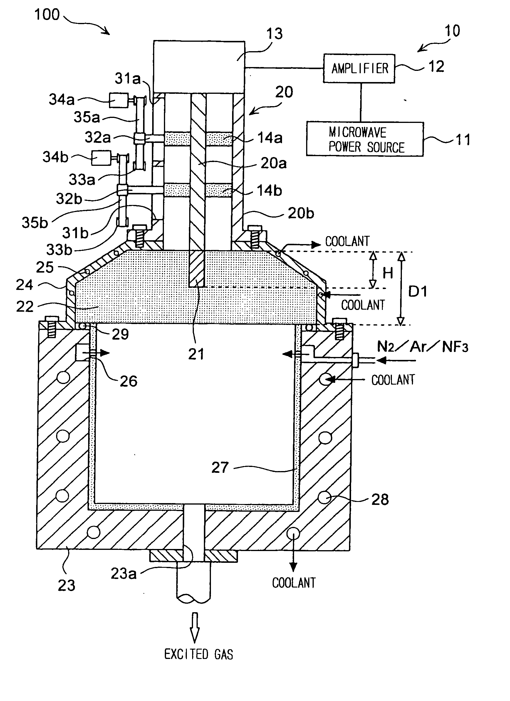
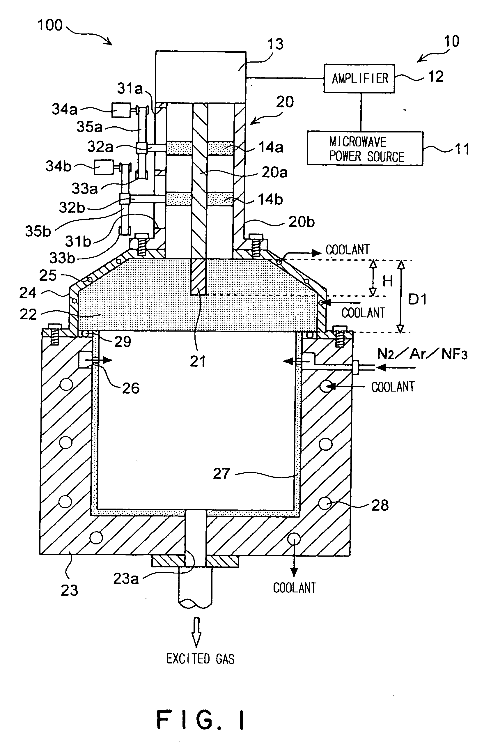
[0033] The embodiments of the present invention are described below in detail with reference to the drawings. FIG. 1 is a cross-sectional view showing a schematic structure of a plasma generating apparatus 100. The plasma generating apparatus 100 broadly has a microwave generating apparatus 10, a coaxial waveguide 20 comprising an inner tube 20a and an outer tube 20b, a monopole antenna 21 attached to the end of the inner tube 20a, a resonator 22 and a chamber 23.

[0034] The microwave generating apparatus 10 has a microwave power source 11 such as magnetron which generates microwaves of 2.45 GHz frequency for example, an amplifier 12 which regulates the microwaves generated by the microwave power source 11 to a predetermined output level, an isolator 13 which absorbs the reflected microwaves which are output from the amplifier 12 and returning to the amplifier 12, and slug tuners 14a and 14b which are attached to the coaxial waveguide 20. One end of the coaxial waveguide 20 is attac...


PUM

PropertyMeasurementUnit
Poweraaaaaaaaaa
Corrosion propertiesaaaaaaaaaa
Wavelengthaaaaaaaaaa

Abstract

A compact plasma generating apparatus providing high efficiency of plasma excitation is presented. A plasma generating apparatus (100) comprises a microwave generating apparatus (10) for generating microwaves, a coaxial waveguide (20) having a coaxial structure comprising an inner tube (20a) and an outer tube (20b), a monopole antenna (21) being attached to one end of said inner tube (20a), for directing the microwaves generated by said microwave generating apparatus (10) to the monopole antenna (21), a resonator (22) composed of dielectric material for holding the monopole antenna (21), and a chamber (23) in which a specific process gas is fed for plasma excitation. The chamber (23) has an open surface and the resonator (22) is placed on this open surface, and the process gas is excited by the microwaves radiated from the monopole antenna (21) through the resonator (22) into the interior of the chamber (23) to generate plasma.

Description


Claims


Application Information

Patent Timeline
Owner TOKYO ELECTRON LTD
Why Eureka
Try Eureka