Power supply for resistance welding units

a technology for resistance welding and power supply, which is applied in the direction of resistance welding apparatus, welding electric supply, welding electric supply, etc., can solve the problems of not being able to bridge greater distances, increasing space requirements, and requiring new inversion using a relatively complex circuit configuration

Inactive Publication Date: 2006-06-29
BOSCH REXROTH AG
View PDF7 Cites 8 Cited by
  • Summary
  • Abstract
  • Description
  • Claims
  • Application Information

AI Technical Summary

Benefits of technology

[0005] An example embodiment of the present invention may provide for the implementation of resistance welding devices that may be as small as possible and that may allow for a simple expansion depending on the particular application.

Problems solved by technology

The foregoing is believed to be practical for supplying components within a single unit, but not for bridging greater distances and for supplying several autonomous resistance welding systems, e.g., welding robots within a production line in the automotive industry.
Moreover, a new inversion using a relatively complex circuit configuration may be required for generating the welding current.
This may entail a greater space requirement.

Method used


Image

  • Power supply for resistance welding units
  • Power supply for resistance welding units

Examples


Embodiment Construction

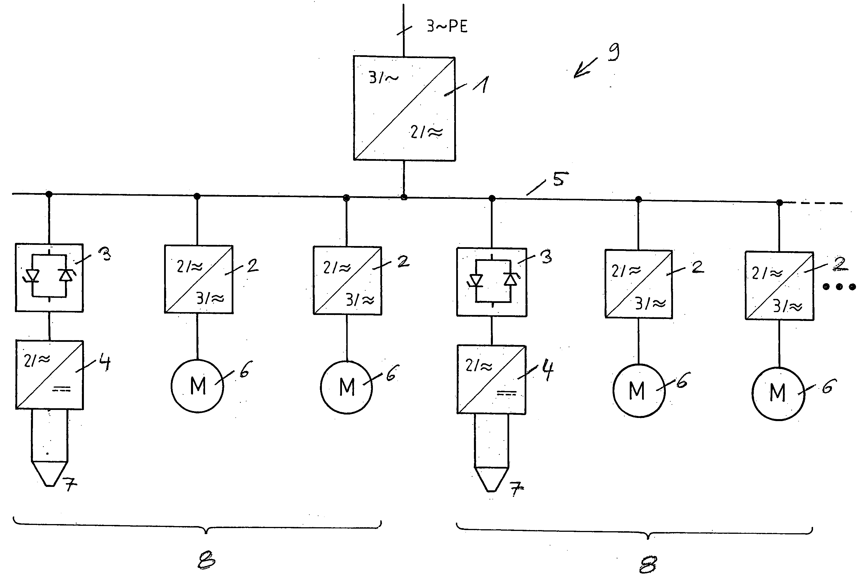
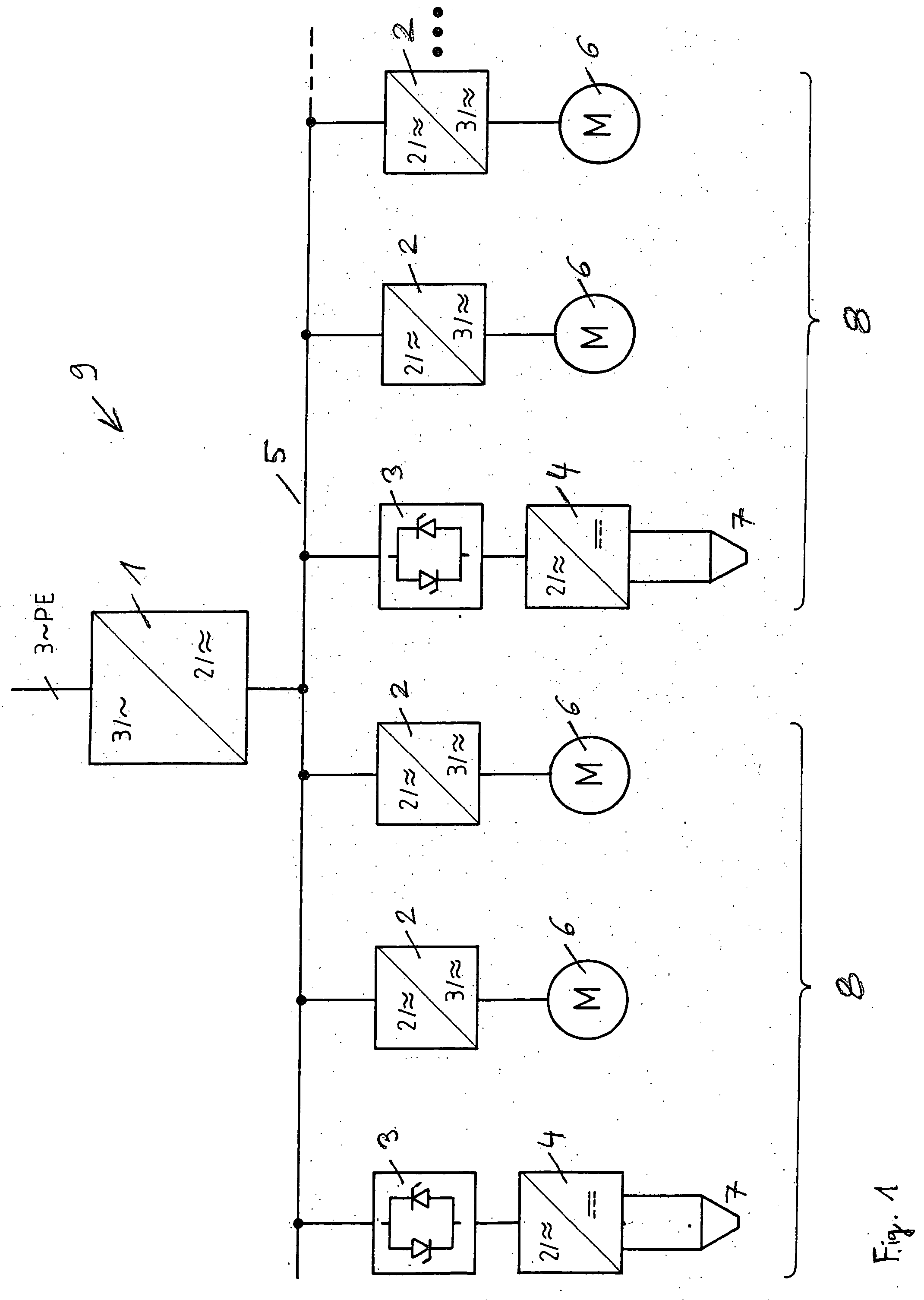
[0045]FIG. 1 illustrates a main converter 1, a drive converter 2, a welding converter 3, welding converters with rectifier 4, an a.c. voltage intermediate circuit 5, welding clamp motors 6, welding clamps 7, two resistance welding devices 8 formed by components 3, 4, 7, 2, 6 or an all-comprehensive resistance welding system having a modular power supply 9. Each resistance welding device 8 normally also includes its own welding control installed in a decentralized manner.

[0046] Main converter 1 works with a three-phase a.c. voltage having a system frequency at its input of 50 / 60 Hz (Germany / U.S.A.). It converts this three-phase a.c. voltage into a two-phase a.c. voltage having an intermediate circuit system frequency of, e.g., about 1 kHz. This intermediate circuit system frequency of about, e.g., 1 kHz, however, is merely exemplary. Usually, the intermediate circuit system frequency at the output of main converter 1, however, will be between, e.g., 1 kHz and 10 kHz and thus may be ...


PUM

PropertyMeasurementUnit
distancesaaaaaaaaaa
frequencyaaaaaaaaaa
frequencyaaaaaaaaaa

Abstract

A device for resistance welding includes a welding clamp housing, a welding transformer, a welding clamp, a welding clamp drive for operating welding clamp and a power supply by alternating supply voltage, which may be built as small as possible and may be simple to expand, the power supply being implemented by a main converter and by drive and welding converters, the output of main converter being connected to the inputs of drive and welding converters, the inputs of drive and welding converters being connected to one another and the connection being implemented by an a.c. voltage intermediate circuit.

Description

CROSS-REFERENCE TO RELATED APPLICATIONS [0001] The present application claims priority to Application No. 10 2004 058 614.4, filed in the Federal Republic of Germany on Dec. 4, 2004, which is expressly incorporated herein in its entirety by reference thereto. FIELD OF THE INVENTION [0002] The present invention relates to a power supply for resistance welding units. BACKGROUND INFORMATION [0003] The hierarchical structure of a device for resistance welding is described in German Published Patent Application No. 101 14 323 (see, e.g., FIG. 3). With the aid of a rectified, three-phase a.c. power supply, a.c. voltages of variable phase and frequency are generated for the power supply of the welding clamp and the drives. For this purpose, the welding inverter provides a two-phase output voltage and the drive inverter a three-phase output voltage. [0004] The foregoing is believed to be practical for supplying components within a single unit, but not for bridging greater distances and for ...

Claims


Application Information

Patent Timeline
Patent Type & Authority Applications(United States)
IPC IPC(8): B23K11/24
CPCB23K11/241B23K11/243H02J3/00
Inventor STELLWAG, DIETERKLINGER, THOMAS
Owner BOSCH REXROTH AG
Why Eureka
Try Eureka