Vibration-generating small motor and portable electronic apparatus

Inactive Publication Date: 2006-06-29
NAMIKI SEIMITSU HOSEKI KK
View PDF16 Cites 31 Cited by
  • Summary
  • Abstract
  • Description
  • Claims
  • Application Information

AI Technical Summary

Benefits of technology

[0049] Accordingly, as stated above, the present invention enables high connection reliability between the power supply terminal and the electrodes or the power supply lands of the circuit board, which is its object, as well as long-term, stable supply of power (long service life), and it provides the vibration-g

Problems solved by technology

In the case of Patent Reference 1, however, as in the case of power supply terminal 104 shaped as in FIG. 13, the leaf spring undergoes elastic deformation primarily at the bend 104f, and so when the vibrating motor is mounted in the electronic equipment, there is a separation between the bend 104f and the contacts 104d; this causes the drawback that use of the vibration function or impact from dropping the equipment can reduce the elasticity of the spring in a short period, which markedly reduces the reliability of connection with the power supply.
Because vibration motors always operate under the adverse condition of vibration, such problems occur frequently.
That does not represent a thorough resol

Method used


Image

  • Vibration-generating small motor and portable electronic apparatus
  • Vibration-generating small motor and portable electronic apparatus
  • Vibration-generating small motor and portable electronic apparatus

Examples


Example

[0064] The constitution of the first embodiment of the present invention is explained in detail below, with reference to FIGS. 1, 2, and 6 through 9.

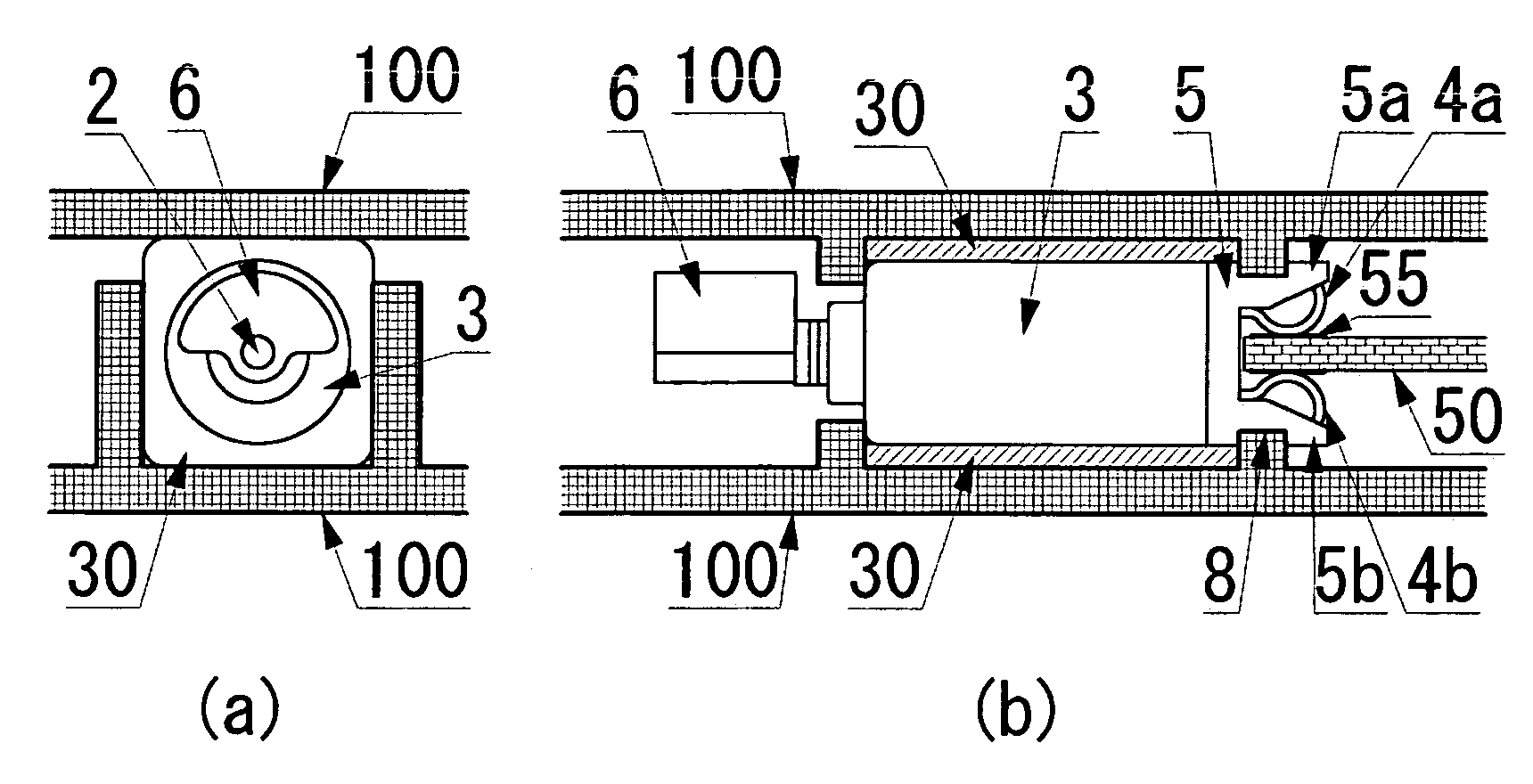
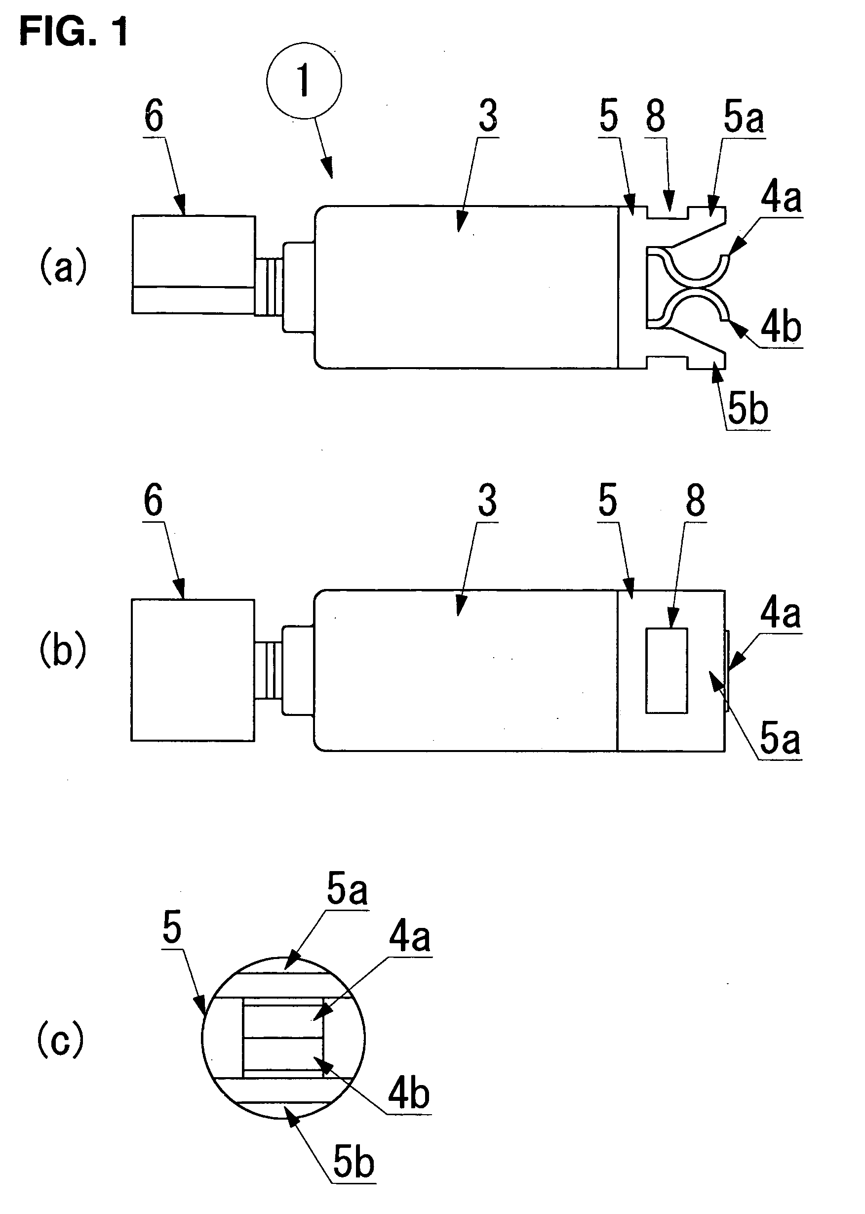
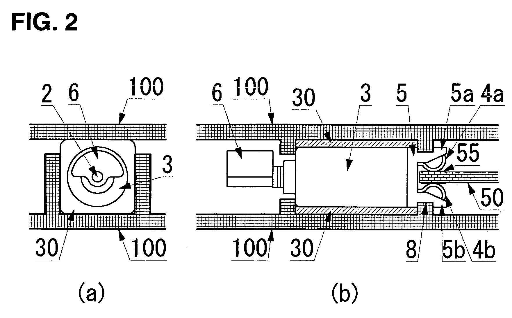
[0065] A vibrating motor 1 in FIG. 1 comprises a motor made up of a substantially cylindrical external housing case 3, a terminal-blade mount 5 located at one end of an external housing case 3 and a power supply terminal 4 comprising terminal blades 4a, 4b mounted thereon, and a mechanism to generate vibrations which comprises an eccentric weight 6 that is fixed to a spindle of the motor. The terminal-blade mount 5 of the motor 1 is substantially cylindrical to match the end of the external housing case 3, and a portion such as stoppers 5a, 5b shown in FIG. 1(a) projects in a direction of the spindle extended to encompass the power supply terminal 4 on both sides.

[0066] Meanwhile, the power supply terminal 4 is assembled as shown in the figure, with a pair of resilient terminal blades 4a, 4b, which face and approach each other, being ...

Example

SECOND EMBODIMENT

[0077] The constitution of the second embodiment of the present invention is explained in detail below, with reference to FIGS. 10 and 11.

[0078] A vibrating motor 11 in FIG. 10 comprises a motor made up of a substantially cylindrical external housing case 13, a terminal-blade mount 15 located at one end of the external housing case 13 and a power supply terminal 14 comprising terminal blades 14a, 14b mounted thereon, and a mechanism to generate vibrations which comprises an eccentric weight 16 that is fixed to a spindle 12, which is supported by a bearing 17 that is molded as a unit with the terminal-blade mount 15. The terminal-blade mount 15 of the motor 11 is positioned on the side and at one end of the external housing case 13, and is substantially perpendicular to the axis of rotation. The pair of facing, resilient, curved leaf spring terminal blades 14a, 14b is similarly positioned to project in a position substantially perpendicular to the axis of rotation....

Example

THIRD EMBODIMENT

[0082] The constitution of the third embodiment of the present invention is explained in detail below, with reference to FIG. 12.

[0083] A vibrating motor 21 in FIG. 12 comprises a mechanism to generate vibrations of the fixed spindle outer rotor type in which the eccentric-weight mechanism to generate vibrations and the stator and rotor drive mechanism are all incorporated within a substantially cylindrical external housing case 23. In (a) of the figure, a reference numeral 27 denotes a cylindrical magnet, and is fixed between flanges 29a, 29b that surround a terminal-blade mount 25 and a spindle 22. That constitutes the stator, along with an external housing case 23, whereas a rotor 28 comprises a wound coil located facing the outer periphery of a magnet 27, along with a yoke and a commutator. An eccentric weight 26 mounted outside the rotor 28 is driven within the external housing case 23.

[0084] With regard to a power supply terminal 24, meanwhile, as shown in F...


PUM


Abstract

The present invention is a vibration-generating small-sized motor that comprises within an external housing case thereof a stator and a rotor, a commutation mechanism, a power supply terminal that connects electrically with an electrode or a power supply land of the electronic equipment, and a terminal-blade mount on which the power supply terminal is mounted, wherein the power supply terminal includes a pair of resilient terminal blades that are located on the terminal-blade mount provided at a face of the external housing case of the motor, facing each other and pressing together, and the electrode or the power supply land on the circuit board are clamped between the resilient terminal blades, whereby the vibration-generating small-sized motor can be electrically connected to the power supply of the electronic equipment. Accordingly, the power supply terminal of the vibrating motor mounted in the portable electronic equipment can be electrically connected to the electrode or the power supply land on the circuit board in the electronic equipment with high reliability and this connection can be maintained continually over a long period.

Description

TECHNICAL FIELD [0001] The present invention relates to a vibration-generating small-sized motor that operates with the capability of a silent vibration alarm (generally called the “manners mode”), to be mounted primarily in a portable electronic equipment (including portable wireless telephones, PHS, small-sized wireless communications equipment, and also various types of portable information processing terminals). Specifically, it relates to a power feed mechanism connecting the motor to a power supply section of a circuit board within the electronic equipment. BACKGROUND ART [0002] There are occasions, such as when people assemble in quiet public places like museums or concert halls, or when one is engaged in business talks or important conferences, in which people nearby would be greatly put out by the sudden ringing of portable electronic equipment (primarily portable telephones). For that reason, varieties of portable electronic equipment have come to be equipped with a silent...

Claims


Application Information

Patent Timeline
IPC IPC(8): H02K11/00H02K7/06B06B1/04H02K5/00H02K5/02H02K5/04H02K5/22H02K5/24H02K7/065
CPCH02K5/00H02K5/225H02K5/24H02K7/061H01R12/721H02K2211/03H02K5/22H02K7/075H02K7/065
Inventor UCHIUMI, HIDEHIROSUZUKI, TOSHIO
Owner NAMIKI SEIMITSU HOSEKI KK
Why Eureka
Try Eureka