Rotor for rotating machine, manufacturing method of rotor and motor for electrically driven power steering

a technology of rotating machines and manufacturing methods, applied in the direction of manufacturing stator/rotor bodies, magnetic circuit rotating parts, magnetic circuit shape/form/construction, etc., can solve the problems of generating noise and vibration, and reducing the accuracy of rotors. achieve the effect of high accuracy and maintaining accuracy

Inactive Publication Date: 2006-06-29
HITACHI LTD
View PDF5 Cites 51 Cited by
  • Summary
  • Abstract
  • Description
  • Claims
  • Application Information

AI Technical Summary

Benefits of technology

[0009] An object of the present invention is to provide a rotor with a high accuracy, a manufacturing method of the rotor and the motor for an electrically driven power steering in a manner that

Problems solved by technology

However, the method of annealing to soften the core entirely causes the following problem.
When the core thus deformed is joined to the shaft, there arises s

Method used


Image

  • Rotor for rotating machine, manufacturing method of rotor and motor for electrically driven power steering
  • Rotor for rotating machine, manufacturing method of rotor and motor for electrically driven power steering
  • Rotor for rotating machine, manufacturing method of rotor and motor for electrically driven power steering

Examples


Embodiment Construction

[0042] The configuration of the motor for an electrically driven power steering according to an embodiment of the present invention will be explained with reference to FIGS. 1 to 7.

[0043] First, the configuration of the motor for an electrically driven power steering according to an embodiment will be explained with reference to FIGS. 1 and 2.

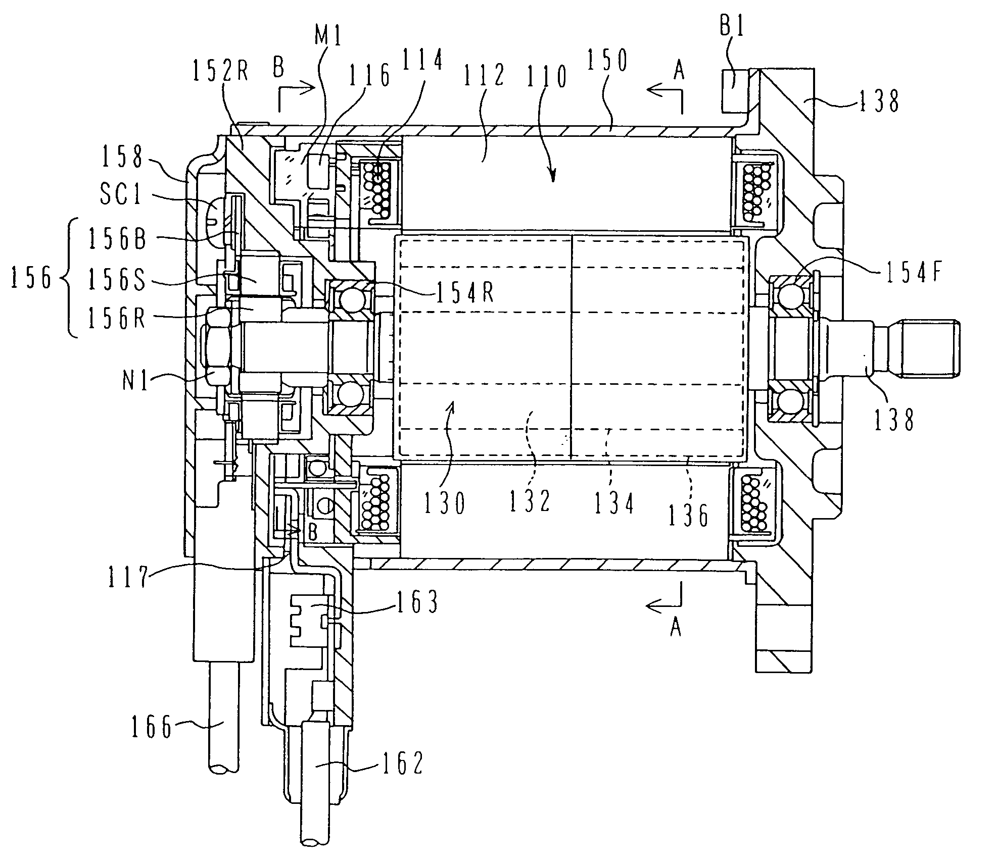
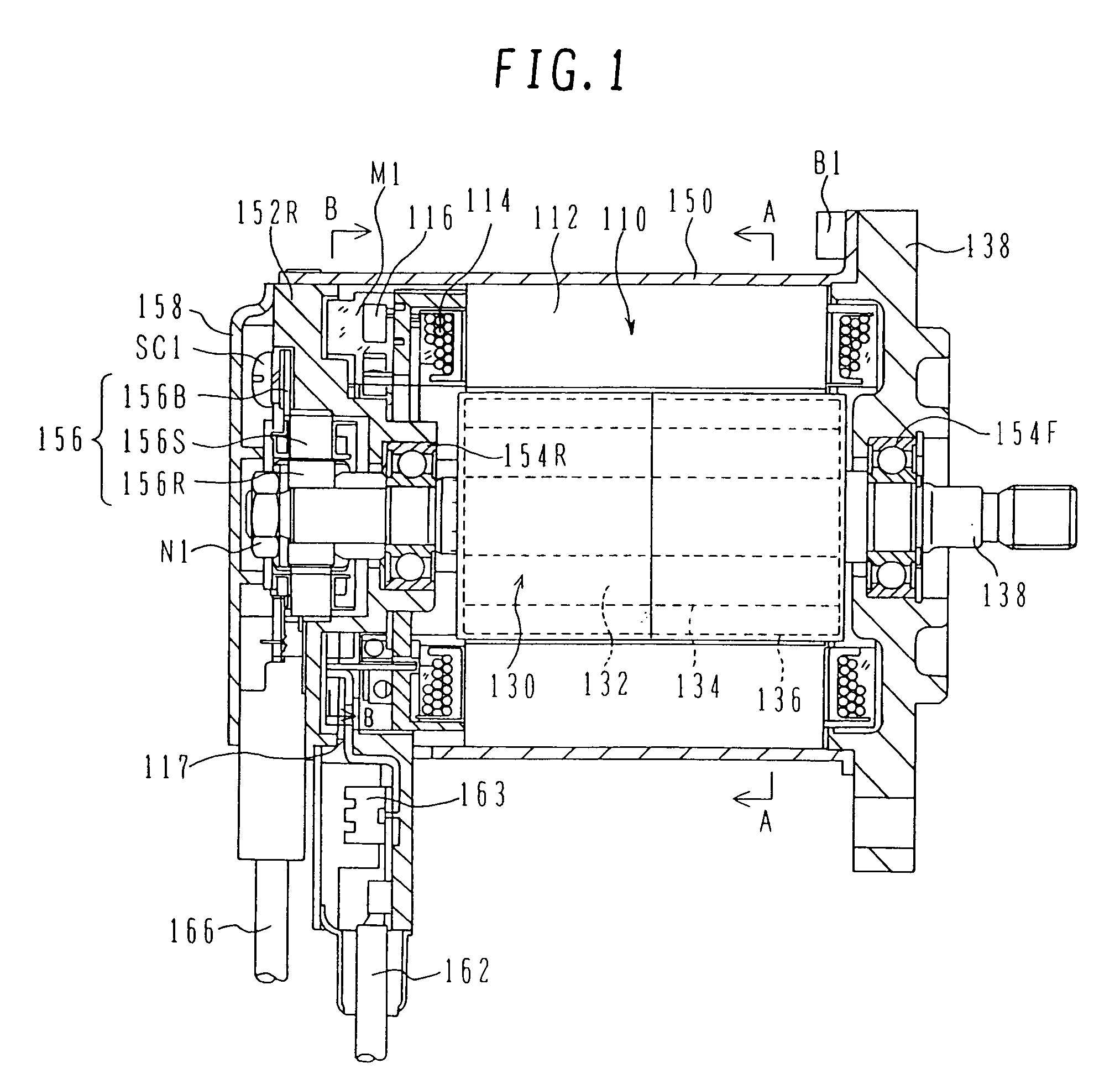
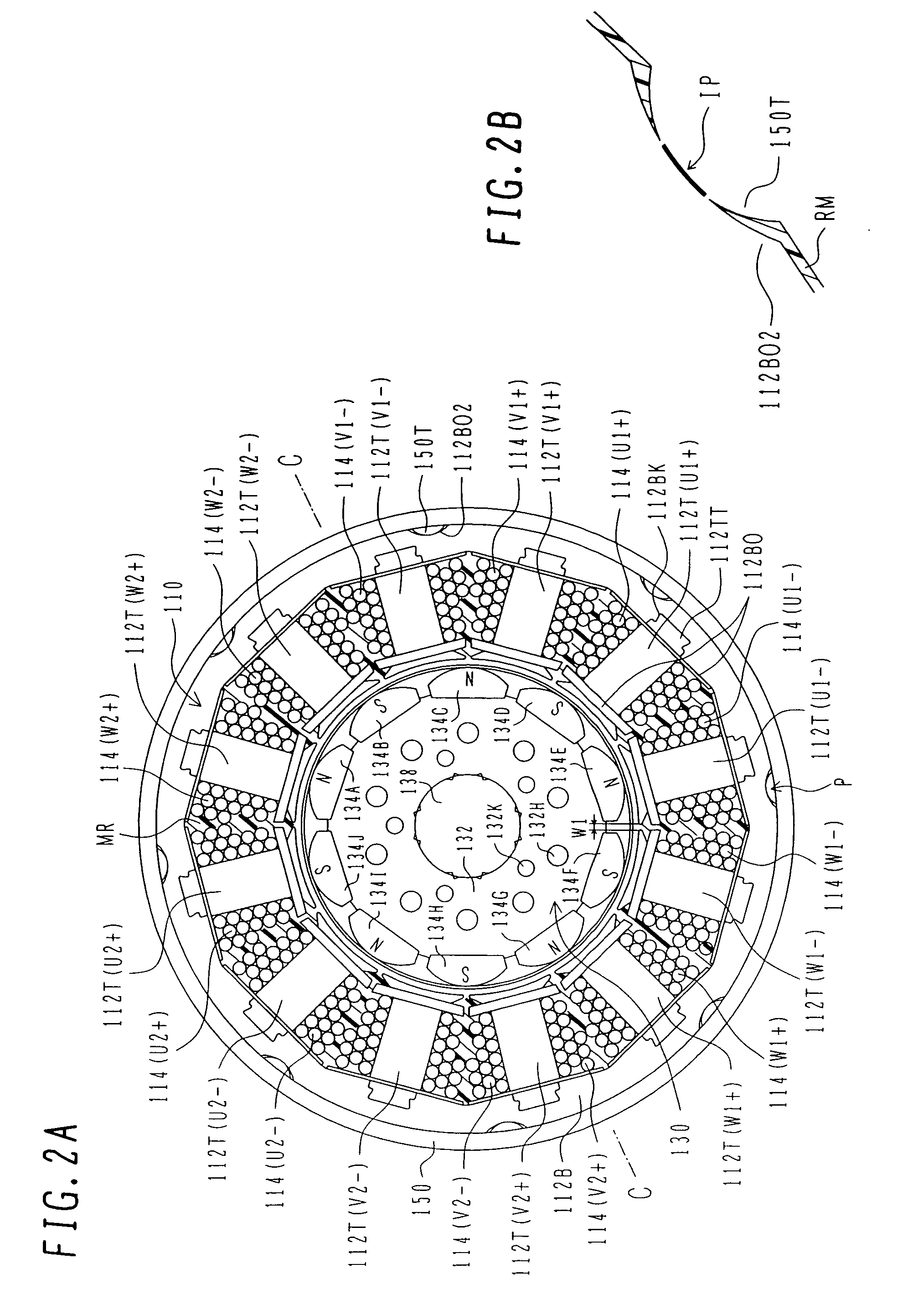
[0044]FIG. 1 is a transversal sectional view showing the configuration of the motor for an electrically driven power steering according to the embodiment. FIGS. 2A and 2B are sectional diagrams of the motor cut along a line A-A in FIG. 1, wherein FIG. 2A is the sectional diagram showing the entirety of the motor and FIG. 2B is the sectional diagram showing the main portion of the motor.

[0045] The EPS motor 100 for an electrically driven a power steering (hereinafter called an EPS motor) is a synchronous motor of a surface magnetic type which includes a stator 110 and a rotor 130 supported so as to be rotatable at the inside of the stator 110...


PUM

PropertyMeasurementUnit
Temperatureaaaaaaaaaa
Areaaaaaaaaaaa
Frequencyaaaaaaaaaa

Abstract

An object of the present invention is to provide a rotor with a high accuracy, a manufacturing method of the rotor and the motor for an electrically driven power steering in a manner that the accuracy of a shaft itself is not degraded, then a core is not applied with excessive deformation, and the shaft and the core are joined while maintaining the accuracy of each of these parts. A rotor is configured by a rotor core which is formed by laminating a plurality of silicon steel plates and has a through hole at the center thereof, and a shaft which is pressed into the through hole of the rotor core. The rotor core is locally annealed only at a portion near the surface of the through hole.

Description

BACKGROUND OF THE INVENTION [0001] 1. Field of the Invention [0002] The present invention relates to the rotor for a rotating machine and the motor for an electrically driven power steering. [0003] 2. Description of the Related Art [0004] Generally, in the conventional rotor, a shaft subjected to the knurling processing by the rolling operation is pressed into and coupled with a rotor core, thereby securing the intensity with respect to the coming-off in the axial direction and the intensity in the rotation direction. However, the baking may occur upon the press-into operation depending on the hardness of the shaft and the hardness of the core, whereby there arise such problems that the coupling accuracy such as a coaxial accuracy degrades and the joint intensity varies. [0005] In order to solve such a problem, there has been employed such a method that the shaft is subjected to the quench hardening thereby to harden the shaft than the core. However, since the shaft is usually thin ...

Claims


Application Information

Patent Timeline
IPC IPC(8): H02K21/12H02K1/06H02K15/14
CPCH02K1/28Y10T29/49009H02K15/02
Inventor HARADA, KOUJIMIRUMACHI, MITSUAKI
Owner HITACHI LTD
Why Eureka
Try Eureka