Non-blocking switch having carbon nanostructures and Mach-Zehnder interferometer

Inactive Publication Date: 2006-06-29
INTEL CORP
View PDF8 Cites 24 Cited by
  • Summary
  • Abstract
  • Description
  • Claims
  • Application Information

AI Technical Summary

Problems solved by technology

Currently available switches have limitations, howev

Method used


Image

  • Non-blocking switch having carbon nanostructures and Mach-Zehnder interferometer
  • Non-blocking switch having carbon nanostructures and Mach-Zehnder interferometer
  • Non-blocking switch having carbon nanostructures and Mach-Zehnder interferometer

Examples


Embodiment Construction

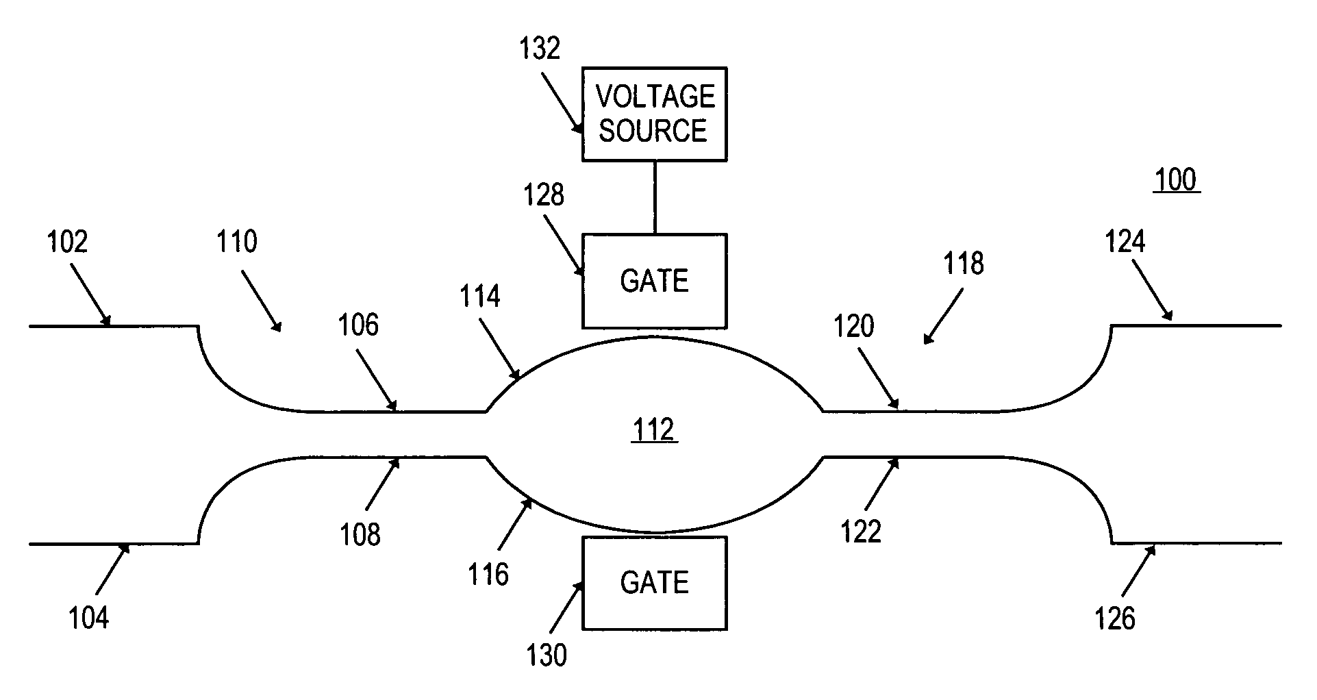
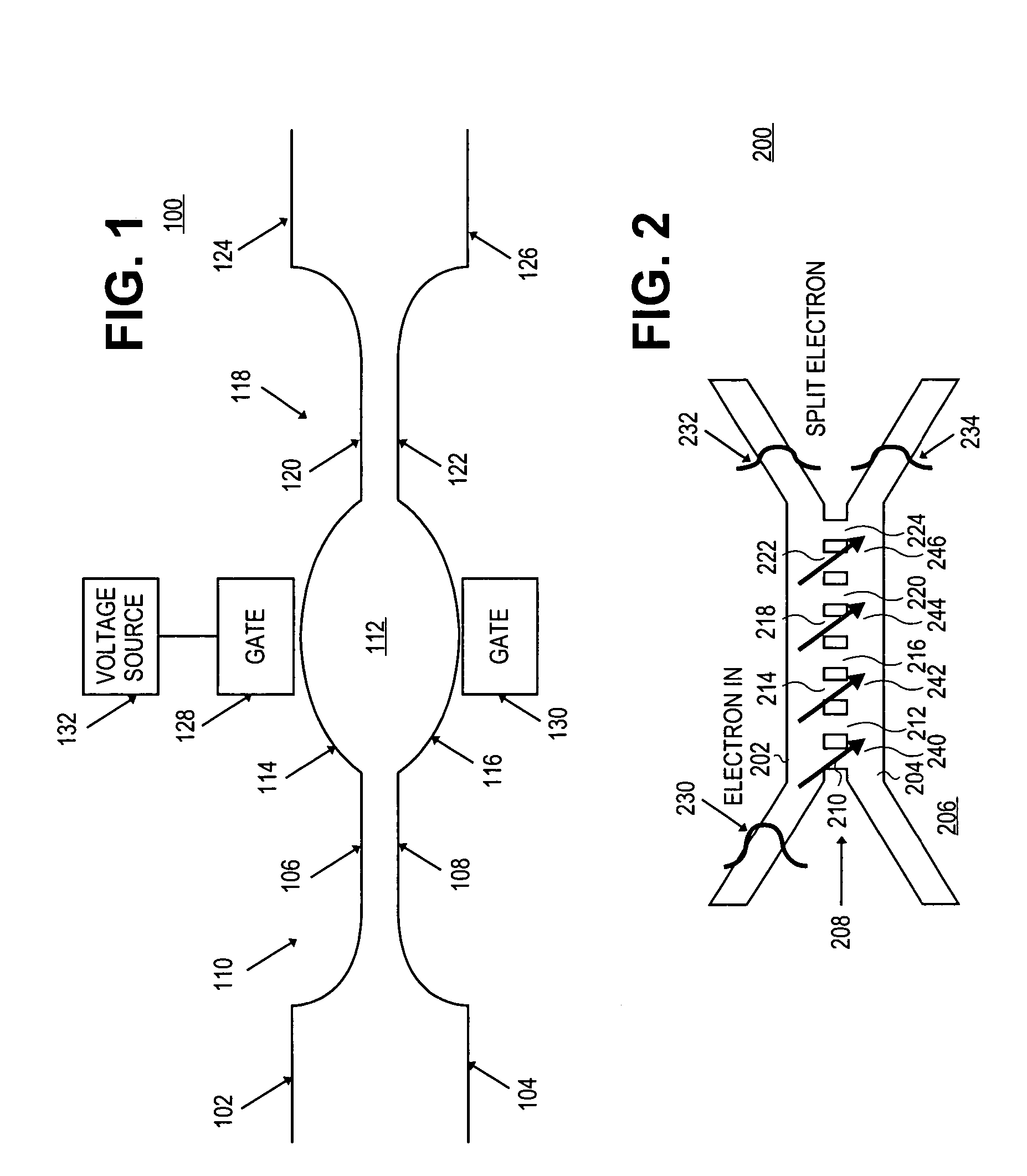
[0015]FIG. 1 is a schematic diagram of a switch 100, such as a non-blocking quantum interference switch, for example, according to an embodiment of the present invention. In the illustrated embodiment, the switch 100 includes two input ports 102 and 104, which are coupled to two electron waveguides 106 and 108, respectively, of a segmented coupler 110. The coupler 110 is coupled to a Mach Zehnder interferometer 112 in that the electron waveguide 106 is coupled to one arm 114 of the interferometer 112 and the electron waveguide 108 is coupled to a second arm 116 of the interferometer 112.

[0016] In the illustrated embodiment, the interferometer 112 is coupled to a second segmented coupler 118 in that the arm 114 is coupled to one electron waveguide 120 of the coupler 118 and the arm 116 is coupled to a second electron waveguide 122 of the coupler 118. The electron waveguide 120 is coupled to an output port 124 and the electron waveguide 122 is coupled to an output port 126. In the il...


PUM


Abstract

In embodiments of the present invention, a non-blocking quantum interference switch includes a segmented electron wave coupler that splits an electron wave and couples its two parts to two arms of a Mach Zehnder interferometer. A voltage may be applied to an interferometer gate electrode to change the phase of the electron wave traveling in that arm. A second segmented electron wave coupler may receive the two electron waves from the interferometer arms and recombine them into one electron wave. If the two electron waves interfere constructively, then the recombined electron wave exits through one switch output port, which may be a “logical zero” switch port, and if the two electron waves interfere destructively, then the recombined electron wave exits through a second switch output port, which may be a “logical one” switch port.

Description

BACKGROUND [0001] 1. Field [0002] Embodiments of the present invention relate to electronic switches and, in particular, to quantum interference switches. [0003] 2. Discussion of Related Art [0004] Switches are used in a variety of devices, such as microprocessors, application specific integrated circuits (ASIC), memory chips, and the like. Currently available switches have limitations, however, in that most of them are based on a field effect. For example, the electric field caused by the applied voltage changes the barrier height for electrons or holes in the switch and thus, either passes or blocks the current through the switch.BRIEF DESCRIPTION OF THE DRAWINGS [0005] In the drawings, like reference numbers generally indicate identical, functionally similar, and / or structurally equivalent elements. The drawing in which an element first appears is indicated by the leftmost digit(s) in the reference number, in which: [0006]FIG. 1 is a schematic diagram of a quantum interference sw...

Claims


Application Information

Patent Timeline
IPC IPC(8): G02B6/10G01S13/00
CPCB82Y20/00G02F1/3136G02F1/3137G02F2202/00G02F2202/36
Inventor NIKONOV, DMITRI E.
Owner INTEL CORP
Why Eureka
Try Eureka