Dual-polarized microstrip patch antenna
- Summary
- Abstract
- Description
- Claims
- Application Information
AI Technical Summary
Benefits of technology
Problems solved by technology
Method used
Image

Examples
Embodiment Construction
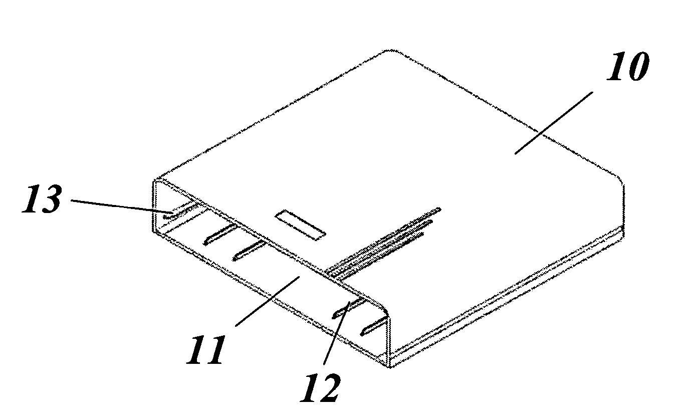
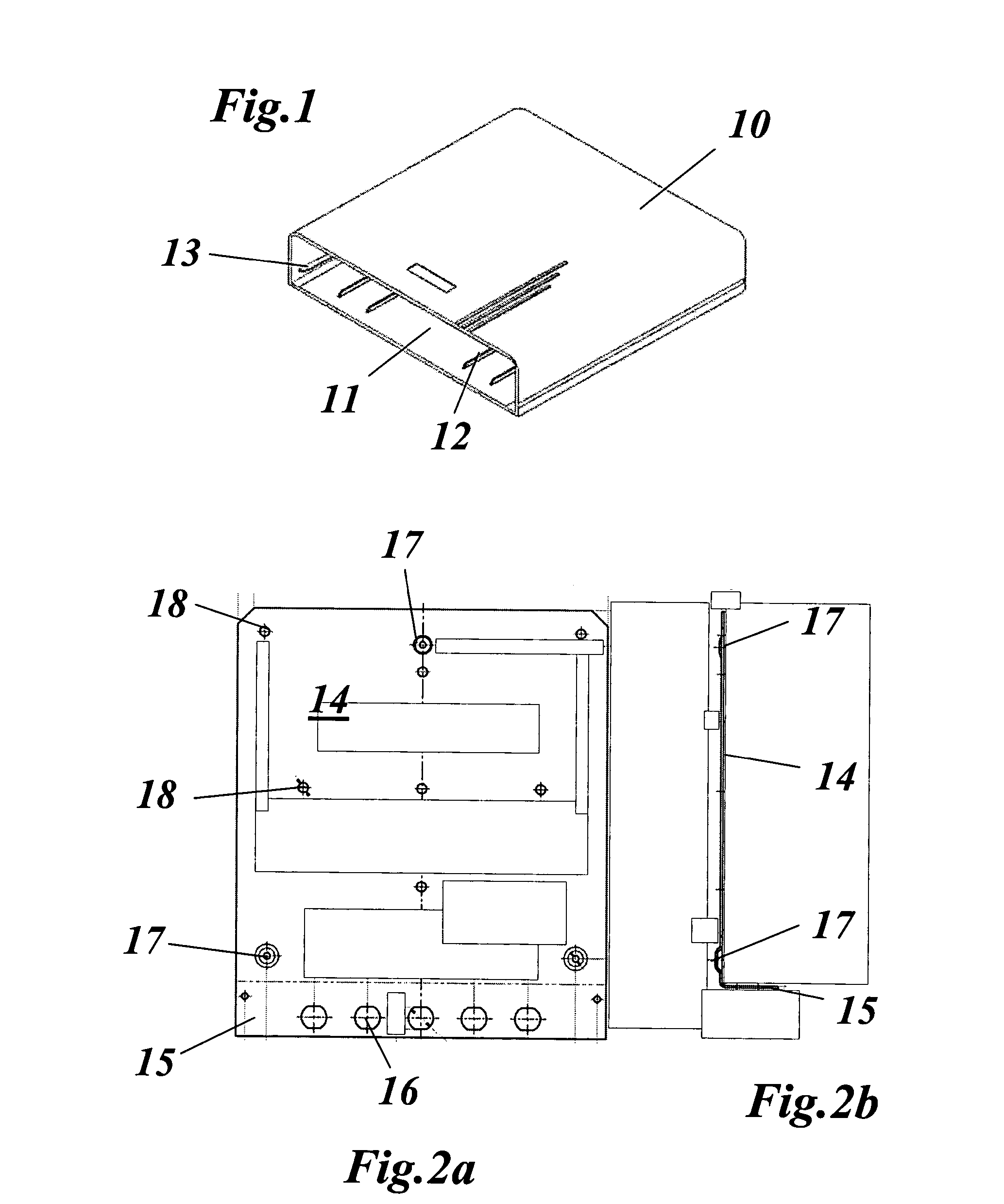
[0024]FIG. 8 shows a perspective illustration of a highly simplified form of a microstrip patch antenna according to one embodiment of the present invention. The antenna 43 essentially comprises a metal sheet 14 and four individual antenna elements EE1-EE4 which are mounted on the metal sheet 14 in a square shaped pattern and at a distance above the upper face of the metal sheet. The shroud 10 of the microstrip patch antenna 43, which is illustrated in FIG. 1, has been omitted in FIG. 8 for clarity. The individual elements EE1-EE4 are composed of a common printed circuit board (PCB) 19, PCB surface mounted patches 20-23 and a feed network 44, and at least one upper patch 29 arranged at a distance above the printed circuit board 19. The upper patch / patches 29 govern increases in the bandwidth.
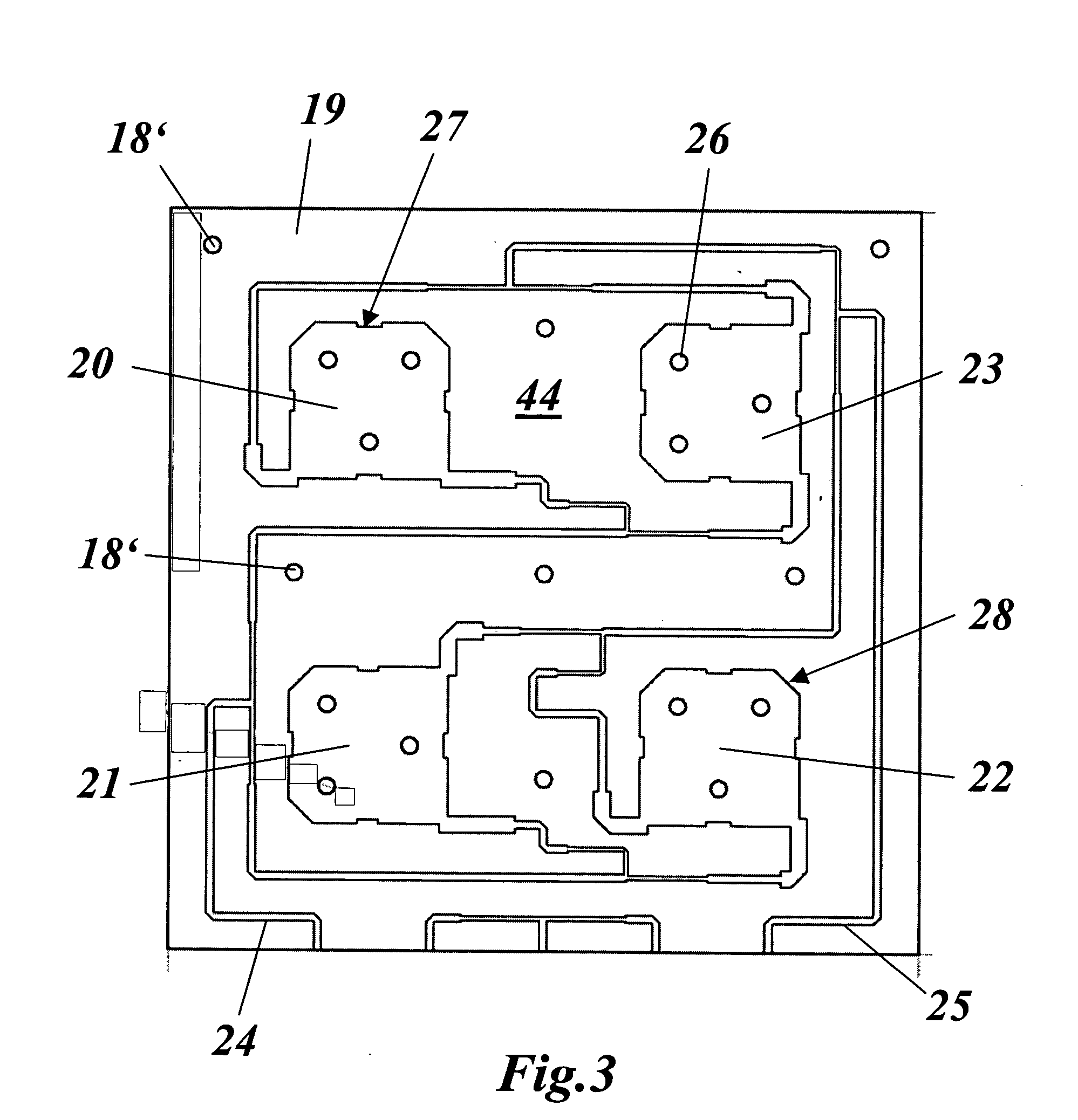
[0025]FIG. 3 depicts one embodiment of printed circuit board 19 in which a feed network 44 is formed on the upper face of printed circuit board 19. The lower face of printed circuit board 19 is...
PUM
 Abstract
Description
Claims
Application Information
 - R&D Engineer
- R&D Manager
- IP Professional
- Industry Leading Data Capabilities
- Powerful AI technology
- Patent DNA Extraction
Browse by: Latest US Patents, China's latest patents, Technical Efficacy Thesaurus, Application Domain, Technology Topic.
© 2024 PatSnap. All rights reserved.Legal|Privacy policy|Modern Slavery Act Transparency Statement|Sitemap