
Liquid container, liquid supply system and recording apparatus using the liquid container, and circuit module for liquid container and substrate

a technology of liquid storage cartridges and circuit modules, which is applied in the direction of printing, other printing apparatus, etc., can solve the problems and achieve the effect of reducing the power consumption of the entire printer

Inactive Publication Date: 2006-06-29
CANON KK
View PDF10 Cites 41 Cited by
  • Summary
  • Abstract
  • Description
  • Claims
  • Application Information

AI Technical Summary

Benefits of technology

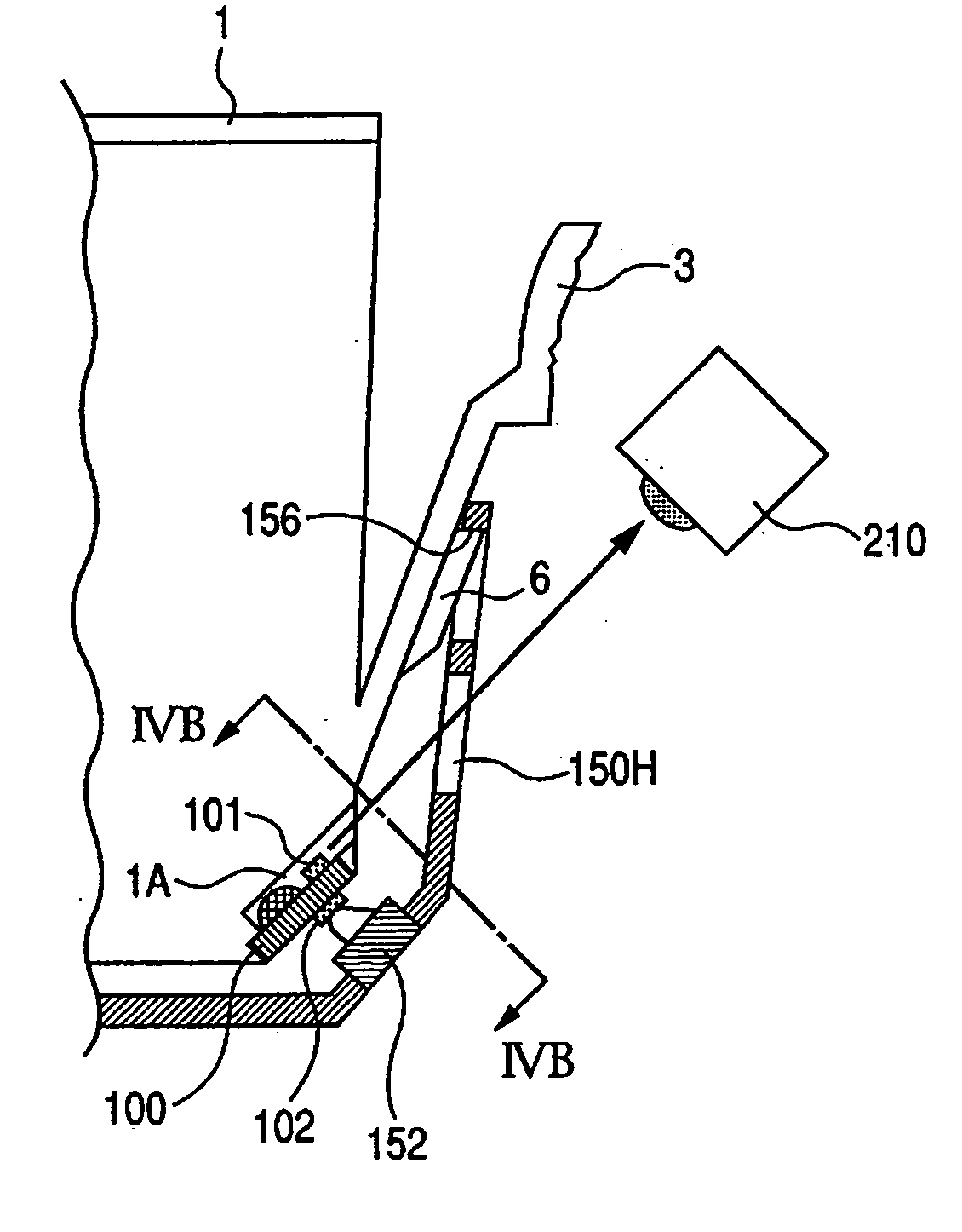
[0013] This invention is made to resolve the above problems, and objects thereof are as follows. A storage element (information retention portion) and an informing portion such as the light emitting portion are provided on the cartridge type ink tank (liquid container) which is mountable on and removable from the printer (recording apparatus), and the information stored in the storage element is communicated to the main body of the recording apparatus. Accordingly, process corresponding to the condition of the respective ink tanks (for example, the amount of the residual ink) is possible, and the power consumption of the entire printer decreases because of the structure of such as the light emitting portion being able to report the condition of the ink tank.
[0014] Another object of the invention is to restrict the increase of the number of wirings for connecting with main body of the recording apparatus side and the complexity when mounting plural ink tanks. Accordingly, the invention provides a liquid container mountable on and removable from a recording apparatus which is capable of mounting plural liquid containers, and which has a apparatus side contact point electrically connectable to a contact point of the liquid container and an electric circuit electrically being connected to the apparatus side contact point and having a wiring to supply a power supply voltage to the plural liquid containers, the liquid container further comprising: the contact point electrically connectable to the apparatus side contact point; an information retention portion capable of retaining at least an individual information with respect to the liquid container; a informing portion; a driving portion for driving the informing portion; a controlling portion capable of accessing the information retention portion in response to a command containing the individual information from the recording apparatus and performing a drive control of the driving portion so as to inform a condition of the liquid container; and voltage level changing means for supplying the voltage as changing a level of the power supply voltage relative to at least one of the controlling portion, the informing portion, and the information retention portion according to the voltage necessary for driving the controlling portion, the informing portion, and the information retention portion.
[0015] According to the invention, by positioning the voltage level changing means, the proper voltage can be supplied to each element (controlling portion, informing portion, and information retention portion) with different driving voltage. Relatively lower voltage is constantly supplied to the controlling portion, thereby driving the information retention portion and the informing portion at the appropriate timing. Thus, plural liquid containers do not require high voltage simultaneously, and the processing appropriate for the necessary events during the series of process of the recording apparatus can be divided, thereby realizing the power saving effects.
[0016] Furthermore, the recording apparatus side is able to supply constant electricity via single power line, thereby restricting the increase in the number of the signal lines connecting to the recording apparatus body side when using plural liquid containers. The invention can flexibly deal with the increase in the number of ink tanks. Therefore, a wide variety of processes at the plural ink tanks are possible without high capacity power supply in the main body of the recording apparatus.

Problems solved by technology

Accordingly, process corresponding to the condition of the respective ink tanks (for example, the amount of the residual ink) is possible, and the power consumption of the entire printer decreases because of the structure of such as the light emitting portion being able to report the condition of the ink tank.

Method used


Image

  • Liquid container, liquid supply system and recording apparatus using the liquid container, and circuit module for liquid container and substrate
  • Liquid container, liquid supply system and recording apparatus using the liquid container, and circuit module for liquid container and substrate
  • Liquid container, liquid supply system and recording apparatus using the liquid container, and circuit module for liquid container and substrate

Examples


Embodiment Construction

[0046] Embodiments of the invention will be explained next with reference to the accompanied drawings.

Example of Mechanical Structure in Which The Invention can be Employed

[0047] Firstly, one example of the mechanical structure of the cartridge and the ink jet recording apparatus using the cartridge in which the invention can be employed will be explained.

Ink Tank (FIG. 1A to FIG. 5B)

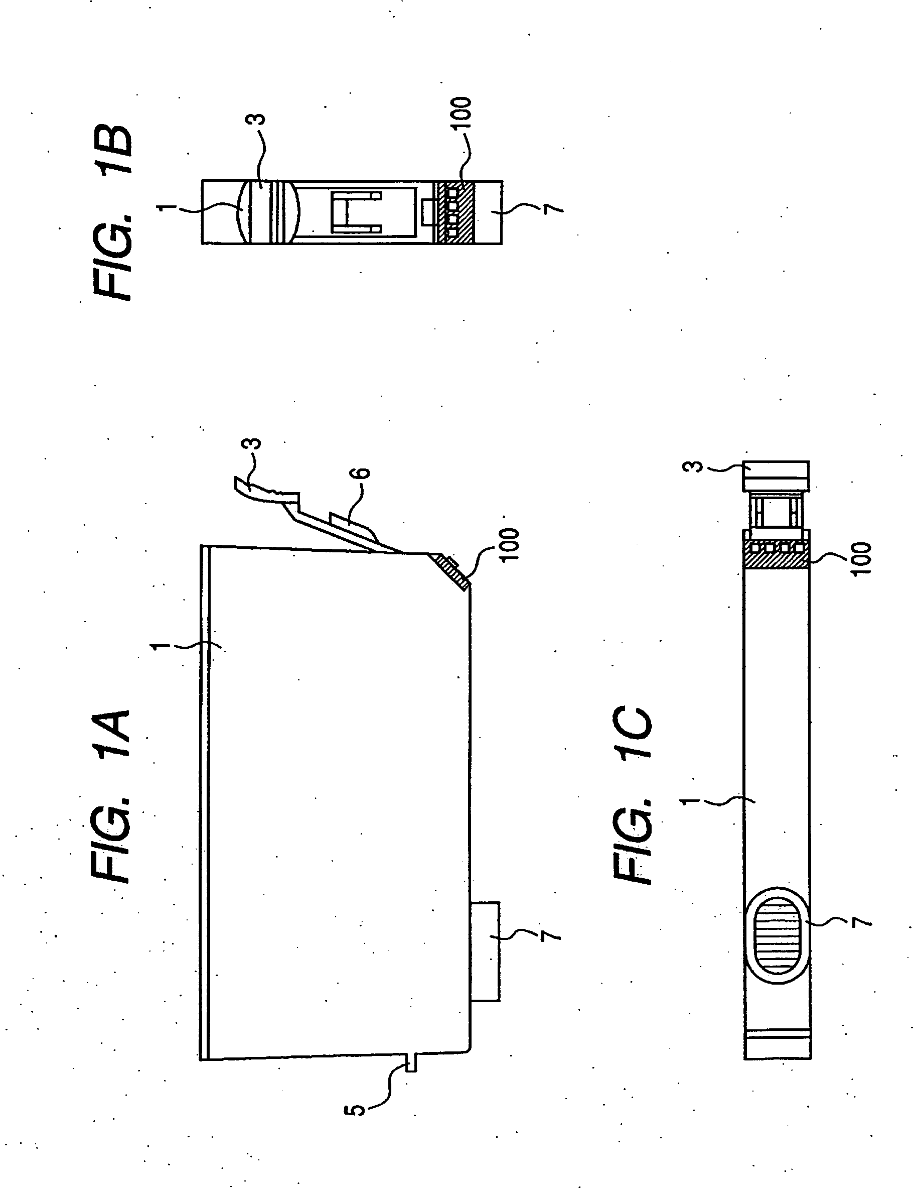
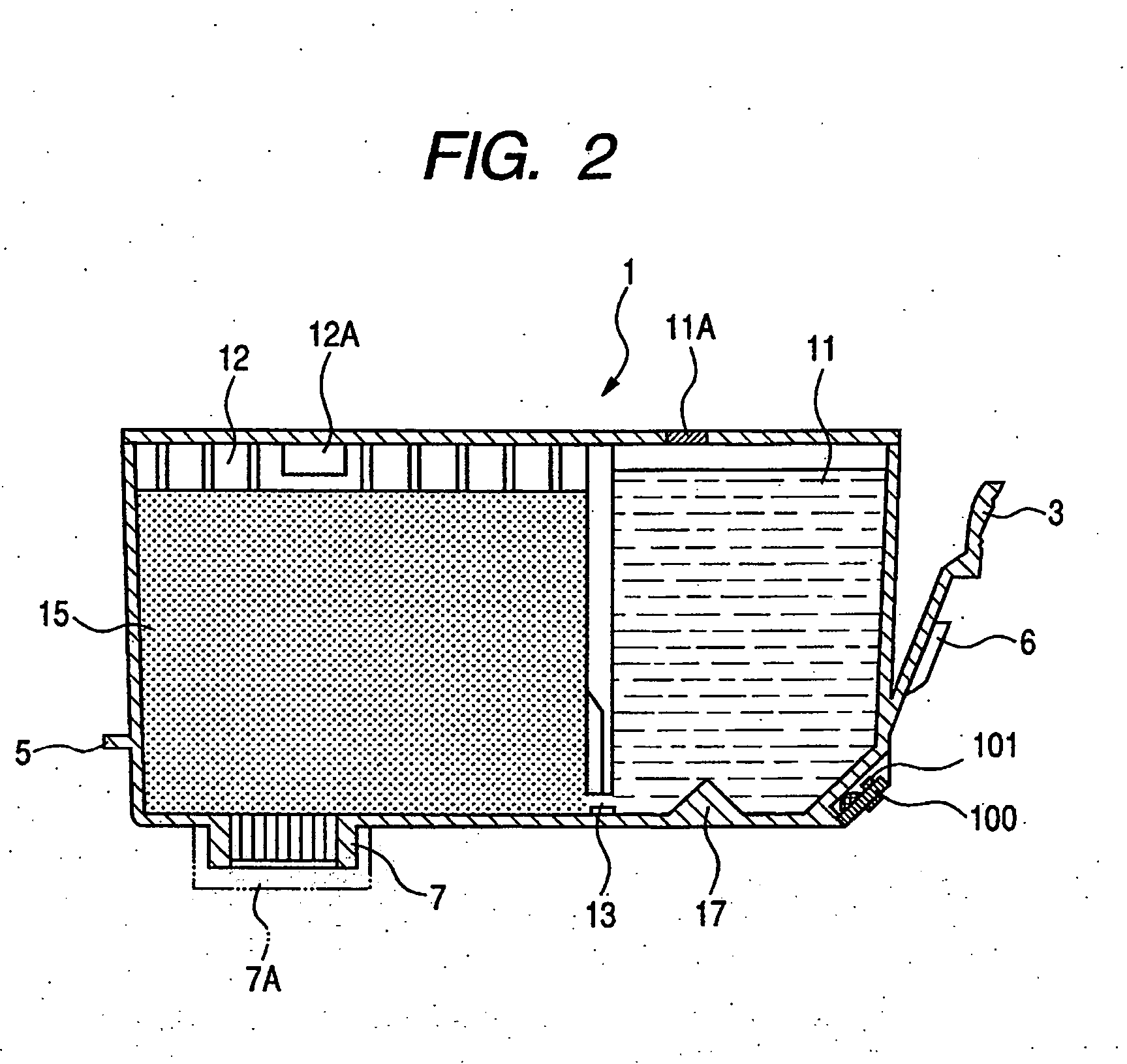
[0048]FIGS. 1A to 1C are a side view, a plan view, and a bottom view of the ink tank according to one embodiment of the liquid container according to the invention respectively, and FIG. 2 is a side cross-section view thereof. In the invention, the front face of the ink tank means a surface facing the user so as to operate such as mounting and removing thereof and to provide the information to the user (later explained LED emission).

[0049] In FIG. 1A to 1C, the ink tank 1 of this embodiment has a supporting member 3, which is supported at a lower portion of a front face of the ink tank 1. The suppo...


PUM


Abstract

The power consumption of the entire recording apparatus is decreased in the structure that the recording element and the light emitting portion are provided on the ink tank, processes according to the amount of the residual ink is performed by communicating information stored in the recording element to the main body of the recording apparatus, and the condition of the ink tank can be informed by emitting light. The ink tank comprises the recording element, the light emitting portion, and the controlling portion driving the the recording element and the light emitting portion at the appropriate timing, and further comprises the voltage level chanigng menas for supplying the appropriate voltage to each thereof. Relatively low voltage is constantly supplied to the controlling portion, thereby driving the recording element and the light emitting portion at the appropriate timing. Accordingly, appropriate processings can be divided according to necessary events during the series of processings for the recording apparatus, thereby realizing the power saving effect.

Description

BACKGROUND OF THE INVENTION [0001] 1. Field of the Invention [0002] This invention relates to a liquid container, a liquid supply system and a recording apparatus using the liquid container, a circuit module for a liquid container and a substrate, and a liquid storage cartridge and particularly relates to the liquid container, the liquid supply system and the recording apparatus using the liquid container, the circuit module for a liquid container, and the substrate which are structured that information of a condition of the liquid container such as the condition of an amount of the residual ink in an ink tank used for the ink jet recording is displayed by driving a light emitting portion such as an LED. [0003] 2. Related Background Art [0004] Recently, diffusion of digital cameras contributes to increase the number of non-PC recording, namely, printing by directly connecting to ink jet printers (hereinafter simply the recording apparatus or printer) functioning as both the digital ...

Claims


Application Information

Patent Timeline
Patent Type & Authority Applications(United States)
IPC IPC(8): B41J2/175
CPCB41J2/17546B41J2/17566B41J2002/17573
Inventor HATASA, NOBUYUKIWATANABE, KENJIROHAYASAKI, KIMIYUKI
Owner CANON KK
Learn More