Microfluidic device including microchannel on which plurality of electromagnets are disposed, and methods of mixing sample and lysing cells using the microfluidic device

Inactive Publication Date: 2006-06-29
SAMSUNG ELECTRONICS CO LTD
View PDF9 Cites 57 Cited by
  • Summary
  • Abstract
  • Description
  • Claims
  • Application Information

AI Technical Summary

Benefits of technology

[0009] The present invention also provides a method of efficiently mixing samples including a magnetic material using the micr

Problems solved by technology

Fluids do not mix well in microchannels of microfluidic devices because they form a laminar flow, and various attempts have been made to solve this problem.
However, the manufacturing process for producing the channels required for such methods is complex and the stream of fluids may be blocked when the channels have a complex 2- or 3-dimensio

Method used


Image

  • Microfluidic device including microchannel on which plurality of electromagnets are disposed, and methods of mixing sample and lysing cells using the microfluidic device
  • Microfluidic device including microchannel on which plurality of electromagnets are disposed, and methods of mixing sample and lysing cells using the microfluidic device
  • Microfluidic device including microchannel on which plurality of electromagnets are disposed, and methods of mixing sample and lysing cells using the microfluidic device

Examples


Example

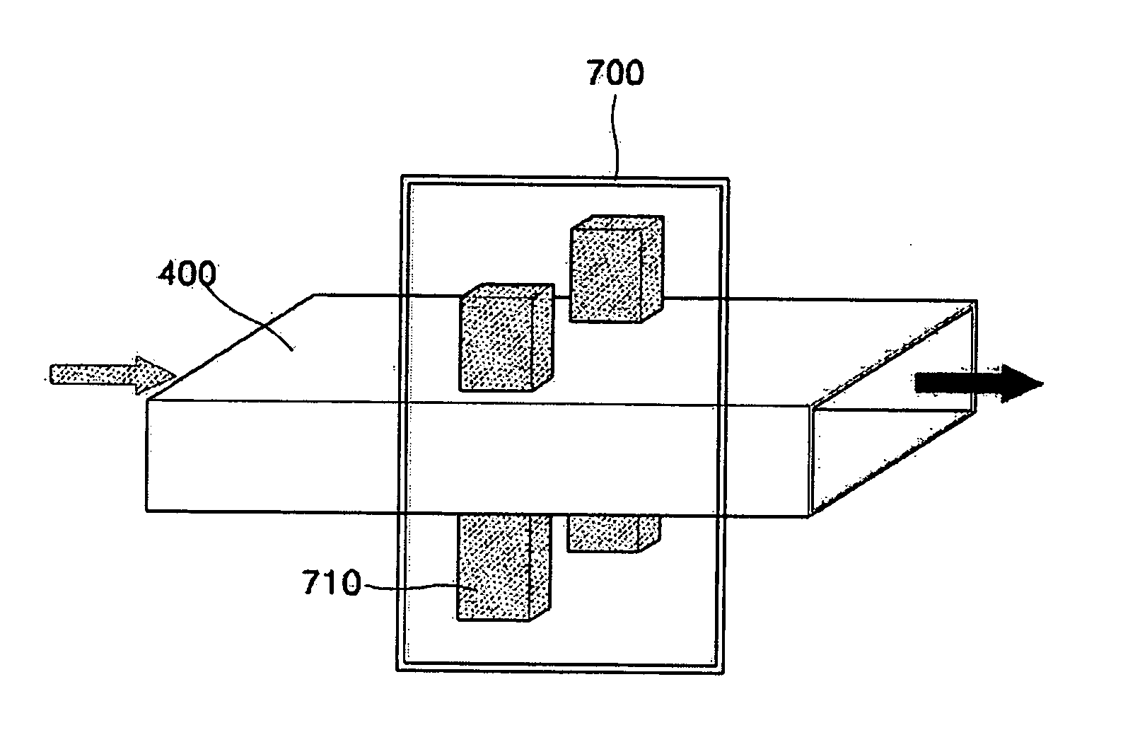
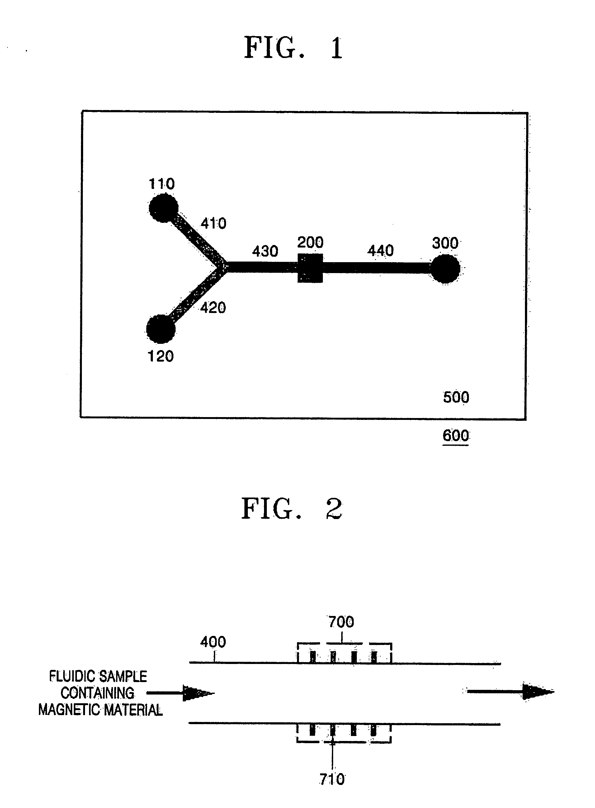
[0023] According to an aspect of the present invention, there is provided a microfluidic device comprising at least one inlet, at least one outlet, and a microchannel connecting the inlet and the outlet and two or more electromagnets disposed on sidewalls of the microchannel and oriented in a predetermined direction with respect to the direction in which the microchannel extends.

[0024] The term “microfluidic device” refers to a device including at least one inlet and at least one outlet which are connected via microchannels. The microfluidic device can include a micro chamber in which a chemical reaction occurs or is analyzed. In the present invention, a cross section of the microchannel may be of any shape, for example, circular, rectangular, or trapezoidal.

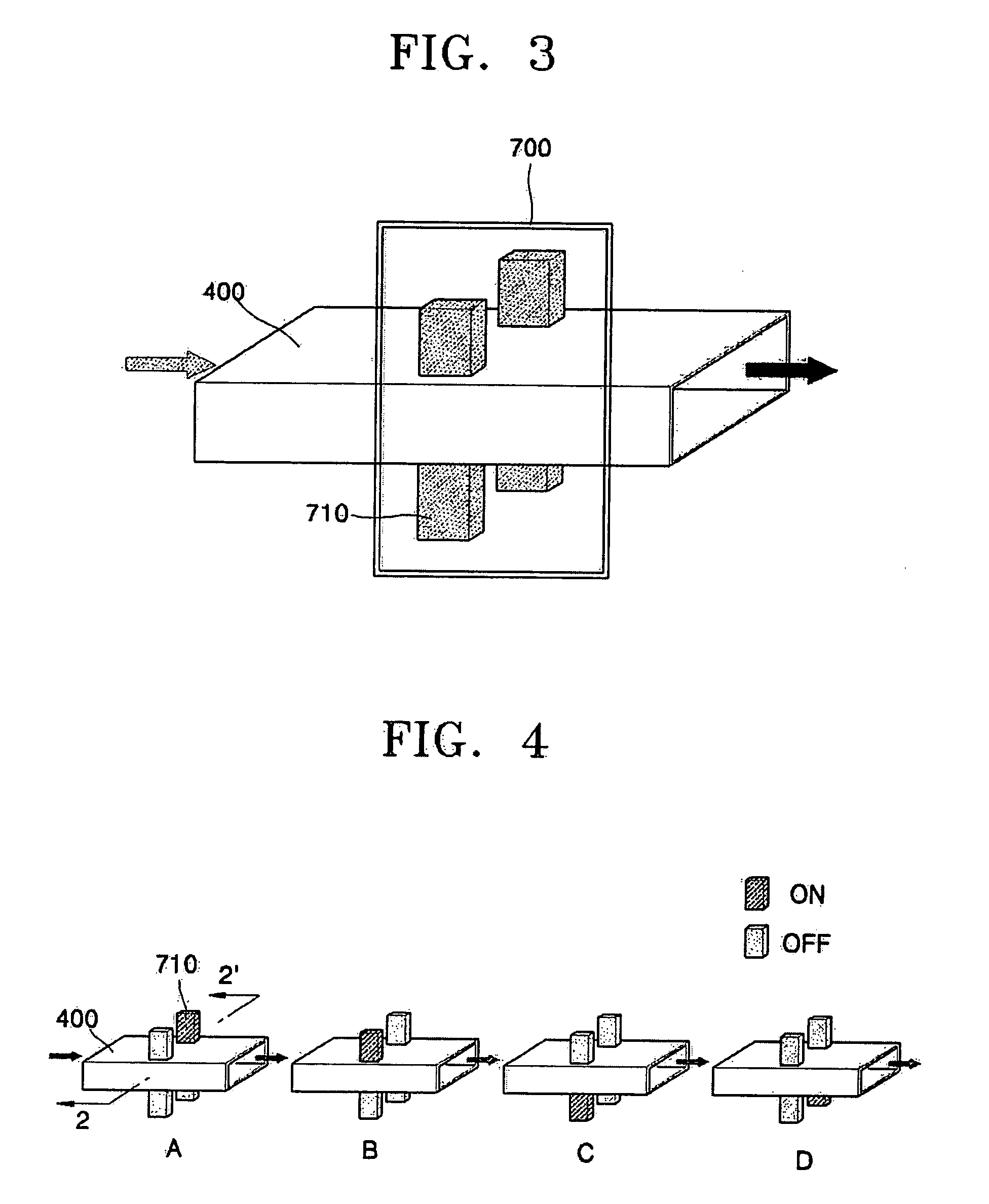
[0025] In the microfluidic device according to the present invention described above, at least two electromagnets are arranged on sidewalls of the microchannel that are oriented in a predetermined direction with respect to the...


PUM


Abstract

Provided is a microfluidic device including at least one inlet, at least one outlet, and a microchannel connecting the inlet and the outlet. The microfluidic device includes two or more electromagnets disposed on sidewalls of the microchannel and oriented in a predetermined direction with respect to the direction in which the microchannel extends.

Description

BACKGROUND OF THE INVENTION [0001] This application claims the priority of Korean Patent Application No. 10-2004-0096152, filed on Nov. 23, 2004 in the Korean Intellectual Property Office, the disclosure of which is incorporated herein in its entirety by reference. [0002] 1. Field of the Invention [0003] The present invention relates to a microfluidic device including a microchannel on which a plurality of electromagnets are disposed, and methods of mixing a sample and lysing cells using the microfluidic device. [0004] 2. Description of the Related Art [0005] Fluids do not mix well in microchannels of microfluidic devices because they form a laminar flow, and various attempts have been made to solve this problem. For example, a method of increasing a contact area between the two fluids at which diffusion occurs by using a complex 2- or 3-dimensional structure and a method of using a magnetic field have been developed. However, the manufacturing process for producing the channels req...

Claims


Application Information

Patent Timeline
IPC IPC(8): B01F13/08
CPCB01F13/0059B01F13/0809C12N1/066B01F33/30B01F33/451B01F33/00B01F33/45
Inventor KIM, JIN-TAEOH, KWANG-WOOKCHO, YOON-KYOUNGPEAK, SANG-HYUNKIM, SOOK-YOUNGPARK, CHIN-SUNGNAMKOONG, KAK
Owner SAMSUNG ELECTRONICS CO LTD
Why Eureka
Try Eureka