
Power supply line communication modem and power supply line communication system

a technology of power supply line and communication modem, which is applied in the direction of power distribution line transmission, single ac network with different frequencies, electric devices, etc., can solve the problems of ineffective suppression of common mode noise, communication interference, and common mode noise along the power line or the cabl

Inactive Publication Date: 2006-06-29
TDK CORPARATION
View PDF2 Cites 45 Cited by
  • Summary
  • Abstract
  • Description
  • Claims
  • Application Information

AI Technical Summary

Benefits of technology

[0007] It is an object of the invention to provide a modem for power-line communications for effectively suppressing common mode noise resulting from a stray capacitance between the ground and a power line or a cable connected to the modem, and to provide a power-line communications system incorporating the modem.
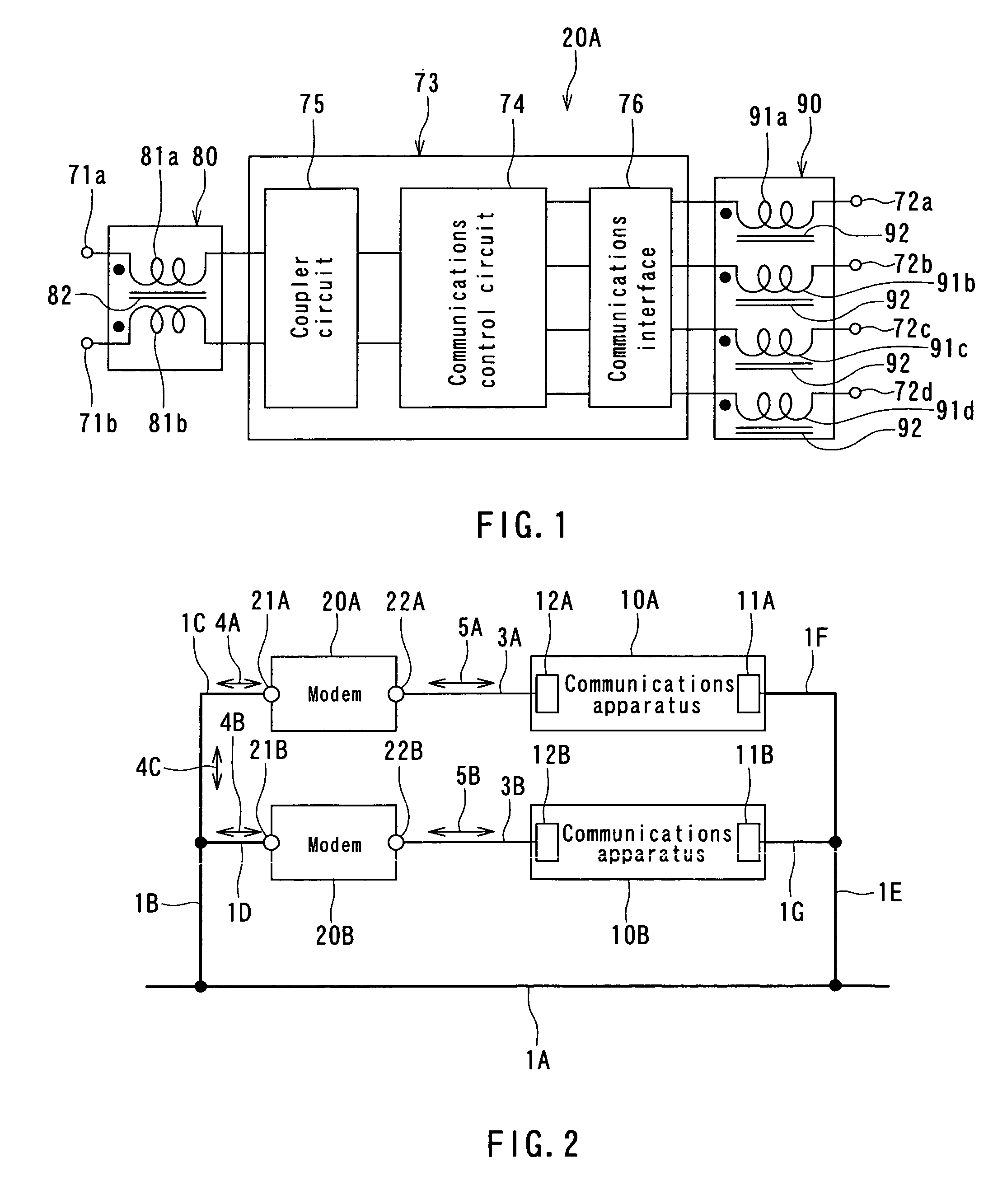
[0010] In the modem of the invention, passing of common mode currents is suppressed at both of the first input / output and the second input / output by the common mode filters one of which is provided between the modem main body and the first input / output and the other of which is provided between the modem main body and the second input / output. It is thereby possible to suppress the emergence of common mode noise.

Problems solved by technology

However, the power-line communications scheme has a problem that communications interference could be caused by noise emerging from apparatuses connected to the power line.
A problem that will now be described occurs in the above-mentioned system including the modem for power-line communications.
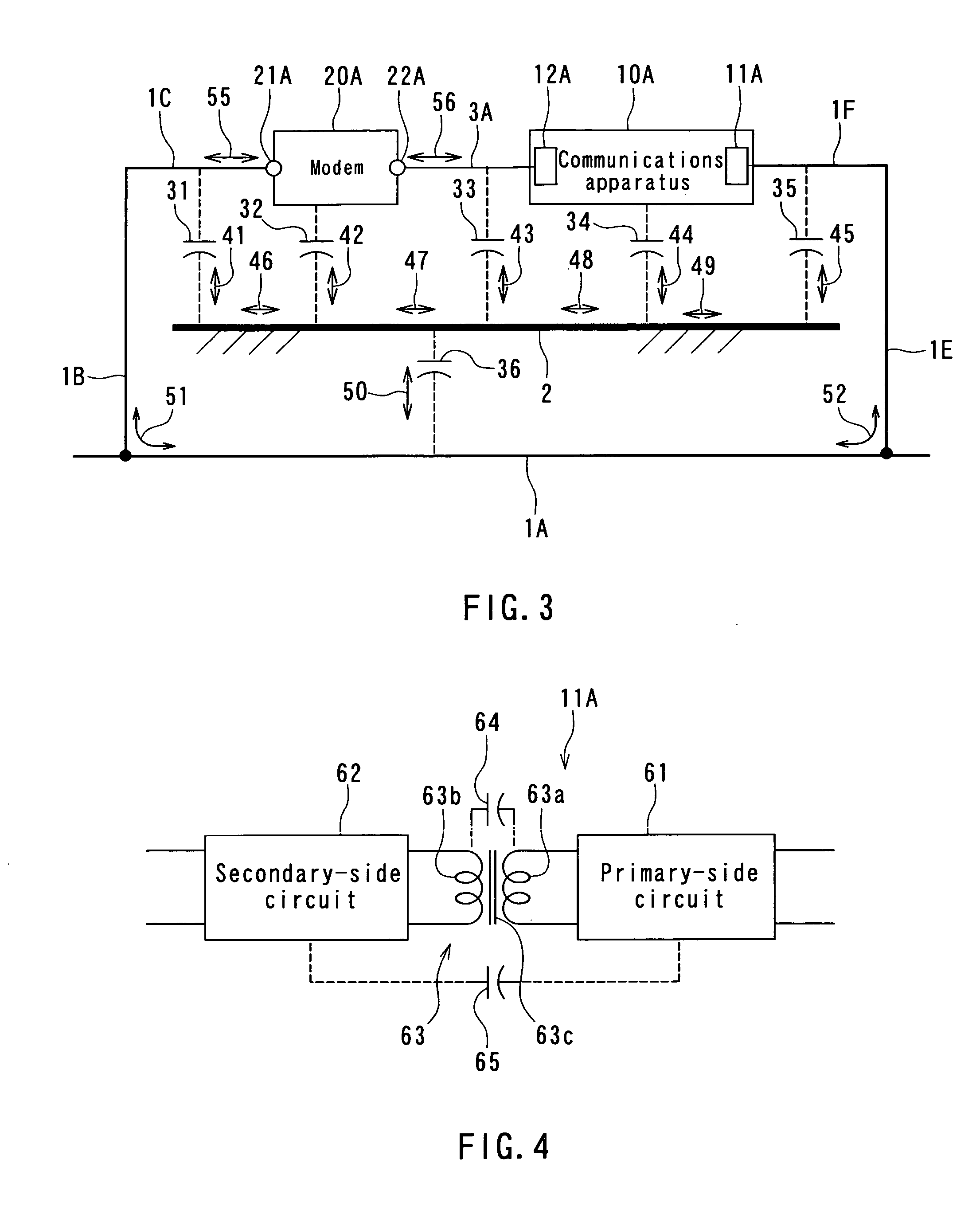
As a result, common mode noise emerges along the power line or the cable.
According to prior art, it is impossible to effectively suppress common mode noise resulting from the stray capacitance in such a manner.

Method used


Image

  • Power supply line communication modem and power supply line communication system
  • Power supply line communication modem and power supply line communication system
  • Power supply line communication modem and power supply line communication system

Examples


Embodiment Construction

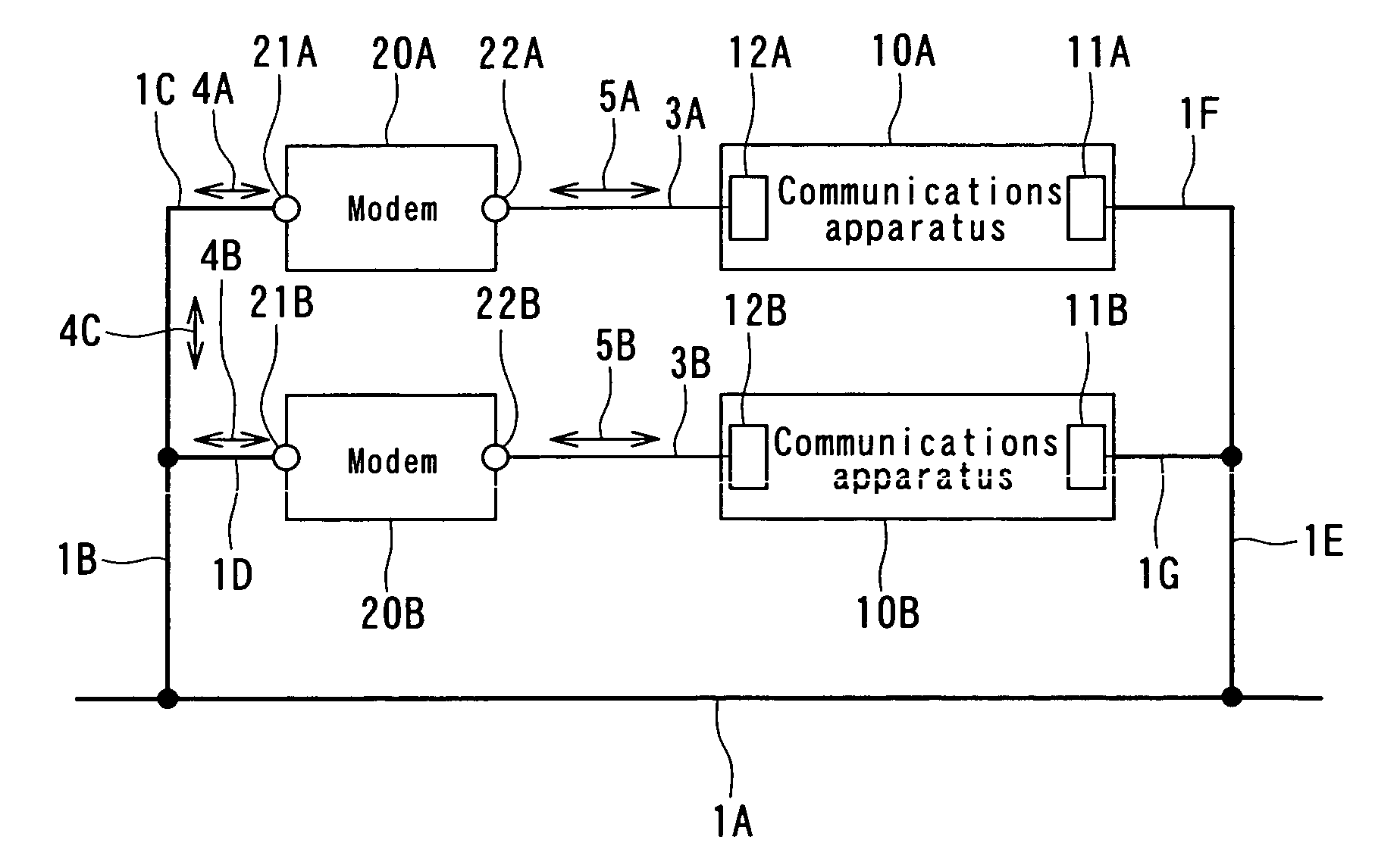
[0021] A preferred embodiment of the invention will now be described in detail with reference to the accompanying drawings. Reference is now made to FIG. 2 to describe an example of configuration of a power-line communications system in which a modem for power-line communications of the embodiment of the invention is employed. The power-line communications system of FIG. 2 comprises: power lines 1A to 1G; two communications apparatuses 10A and 10B performing communications through the use of the power lines 1A to 1G; and modems 20A and 20B for power-line communications of the embodiment. The communications apparatuses 10A and 10B may be information processing apparatuses such as computers or electrical apparatuses having a communications function. Although each of the power lines 1A to 1G is indicated with a single line in FIG. 2, each of them actually includes a plurality of conductor lines.

[0022] The power line 1B is connected to the power line 1A. The power line 1C has an end co...


PUM


Abstract

A modem for power-line communications (20A) comprises input / output terminals (71a and 71b) and input / output terminals (72a to 72d). The input / output terminals (71a and 71b) are connected to a power line and perform input and output of power-line communications signals. The input / output terminals (72a to 72d) perform input and output of data signals from and to a communications apparatus through a cable. The modem (20A) further comprises: a modem main body (73); a common mode filter (80) provided between the modem main body (73) and the input / output terminals (71a and 71b); and a common mode filter (90) provided between the modem main body (73) and the input / output terminals (72a to 72d).

Description

TECHNICAL FIELD [0001] The present invention relates to a modem for power-line communications used in a power-line communications system that performs communications among a plurality of apparatuses through power lines as transmission lines of signals, and to the power-line communications system incorporating the modem for power-line communications. BACKGROUND ART [0002] The needs for data communications in homes have been increasing to accomplish objectives such as the sharing of peripheral equipment of computers and the sharing of data including documents, freeze-frame pictures and moving pictures, and objectives such as games and the Internet. The demands for communications network systems therefore exist not only in offices but also in ordinary households. Communications schemes that can be chosen for constructing a communications network system in the households include the communications scheme utilizing radio, the communications scheme utilizing wires, and the power-line comm...

Claims


Application Information

Patent Timeline
Patent Type & Authority Applications(United States)
IPC IPC(8): H04L5/16H04B3/54H04B3/56
CPCH04B3/56H04B2203/5425H04B2203/5483H04B2203/5491
Inventor WASAKI, MASARUWASAKI, HITOMISAITOH, YOSHIHIRO
Owner TDK CORPARATION
Learn More