Binding-in and pressing machine

a pressing machine and binding technology, applied in the field of binding machines, can solve the problems of limited cycle capacity of this particular construction, and achieve the effect of improving the quality of joint forming and pressing steps, simple and cost-efficient design

Inactive Publication Date: 2006-06-29
KOLBUS
View PDF5 Cites 17 Cited by
  • Summary
  • Abstract
  • Description
  • Claims
  • Application Information

AI Technical Summary

Benefits of technology

[0007] The present invention is based on the objective of making available a binding-in and pressing machine for the joint forming and pressing in of book blocks cased in the book cases, characterized by a comparatively simple and cost-efficient design which can improve the quality of the joint forming and pressing-in steps.

Problems solved by technology

The cycle capacity of this particular construction is limited due to the numerous and partially very time-consuming functional steps in the infeed station, as well as the limited rotational dynamics of the rotor caused by the high forces of inertia.
Although an increase in capacity can be achieved with this pair-by-pair arrangement of the pressing devices on the rotor, this type of arrangement is associated with a substantial additional expenditure for two parallel streams of books, particularly in the infeed and delivery regions of the machine.

Method used


Image

  • Binding-in and pressing machine
  • Binding-in and pressing machine
  • Binding-in and pressing machine

Examples


Embodiment Construction

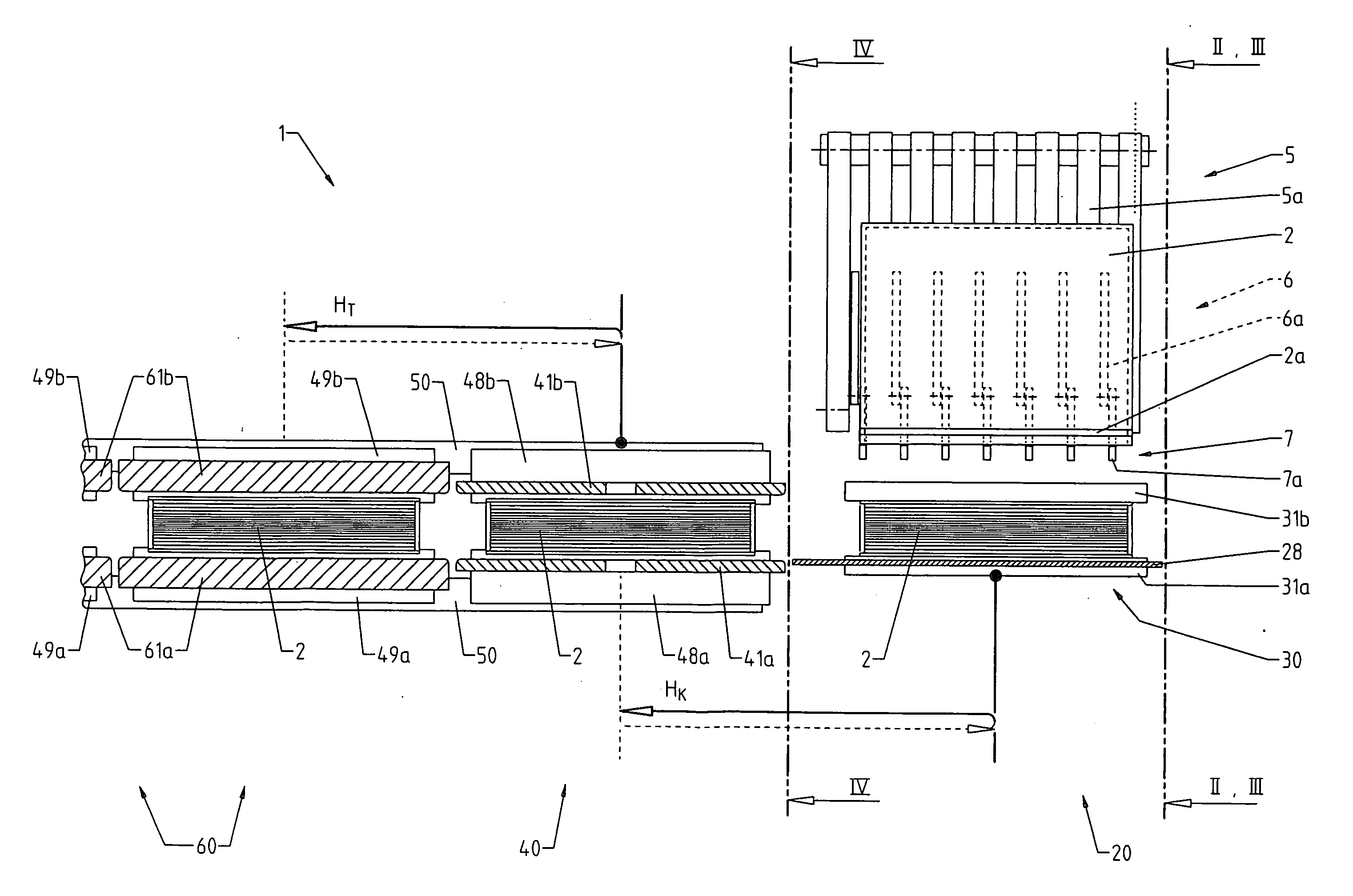
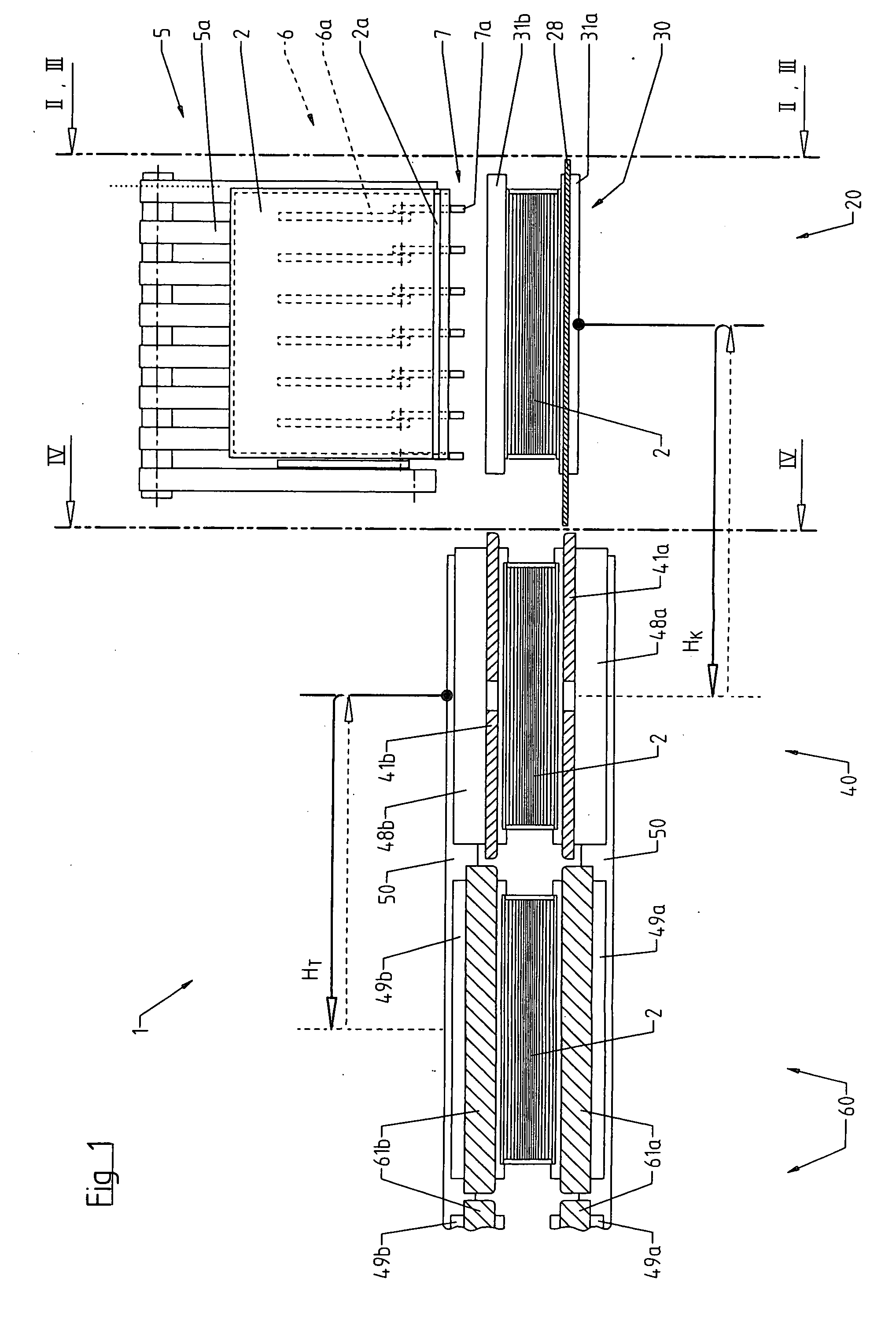
[0014]FIG. 1 shows a schematic top view of a binding-in and pressing machine 1 with pressing stations 60 that are arranged in a straight row and equidistantly spaced apart from one another. The pressing stations respectively contain a pair of oppositely arranged press plates 61a, b that serve for exerting pressure upon the sides of a book 2 and can be adjusted with respect to their mutual distance. Heated joint forming rails 49a, b assigned to the pressing stations 60 are respectively arranged opposite of one another pair-by-pair and adjustable with respect to their mutual distance. The joint forming rails form the book case joints 2a. The joint forming rails 49a, b are situated on a carriage 50 and simultaneously serve as a transport means for advancing the books 2 from station to station in a cyclic fashion with a transport stroke HT. The joint forming rails then return into their starting position in order to receive and transport another book 2.

[0015] According to the preferred...


PUM


Abstract

A binding-in and pressing machine (1) with a plurality of pressing stations (60) and heated joint forming rails situated on a reciprocating carriage (50). An alignment station (20) is provided for aligning the book case joints (2a) at the height of the joint forming rails (49a, b), including a height-adjustable alignment table (21) with rails (22, 23) for supporting the book (2) on the outer edges of its spine and guide elements (28, 6) for centering the book on the alignment table. A separate pre-forming station (40) is also provided that comprises the forming rail (51), clamping plates (41a, b), and joint rails (48a, b) that engage into the book case joints (2a) and counteract a downward movement of at least the book case joints (2a). The books (2) aligned in the alignment station (20) are transferred into the pre-forming station (40) while being clamped in lateral regions near the joints. The effective times available for realizing a functionally safe alignment and a permanent pre-forming of the books are extended due to the assignment of the alignment and pre-forming functions to two separate stations.

Description

BACKGROUND OF THE INVENTION [0001] The present invention pertains to a binding-in and pressing machine for the joint forming and pressing-in of book blocks cased in book cases. [0002] After casing-in the book block into the book case, a crease-free and permanent bond between the end sheets of the book block and the inner sides of the book is achieved by pressing-in the book. In industrial bookbinding, this full-surface pressing step is carried out on so-called binding-in and pressing machines together with the joint forming process, in which the book case joints are formed and glued. [0003] For example, U.S. Pat. No. 2,921,322 describes a book pressing and joint forming machine that is assembled into a production line together with a casing-in machine. The book pressing and joint forming machine comprises a plurality of pressing stations that are arranged in a straight row and equidistantly spaced apart from one another, wherein each pressing station contains a pair of press plates ...

Claims


Application Information

Patent Timeline
Patent Type & Authority Applications(United States)
IPC IPC(8): B42C13/00
CPCB42C5/02B42C13/003Y10S412/902
Inventor BROMMER, CARSTENMEINEKE, TORSTEN
Owner KOLBUS
Why Eureka
Try Eureka