Multi-blade centrifugal blower

a centrifugal blower and multi-blade technology, applied in the direction of liquid fuel engines, marine propulsion, vessel construction, etc., can solve the problem of petty improvement

Inactive Publication Date: 2006-06-29
DENSO CORP +1
View PDF1 Cites 16 Cited by
  • Summary
  • Abstract
  • Description
  • Claims
  • Application Information

AI Technical Summary

Benefits of technology

[0011] In view of the above-described disadvantage, it is an object of the present invention to provide a multi-blade centrifugal blower having an impeller wheel with increased work capacity. Work efficiency improvement and noise reduction of the multi-blade centrifugal blower are also considered.
[0013] Therefore, air readily flows in from the rotation shaft direction in the space which is between the adjacent blades and near the suction portion. Thus, exfoliation is decreased. The inefficacious zone where the main air flow does not pass is reduced. Accordingly, the air flowing speed at an outlet of the impeller wheel is uniformed throughout the blade width (which is dimension in rotation shaft direction), so that work capacity of the impeller wheel is increased.
[0015] Accordingly, noise of the multi-blade centrifugal blower can be reduced with reference to FIG. 17.
[0017] Accordingly, the fan efficiency of the multi-blade centrifugal blower can be improved with reference to FIG. 18.
[0019] Thus, air at the taper portion can be readily sucked, because actual inflow angles are substantially independent of the rotation-shaft-direction positions of the taper portion and the inlet angles throughout the taper portion are set substantially equal to each other. Air flow in the rotation shaft direction and that in the diameter direction are considered in the actual inflow angle.

Problems solved by technology

Therefore, the improvement effect is petty.

Method used


Image

  • Multi-blade centrifugal blower
  • Multi-blade centrifugal blower
  • Multi-blade centrifugal blower

Examples


first embodiment

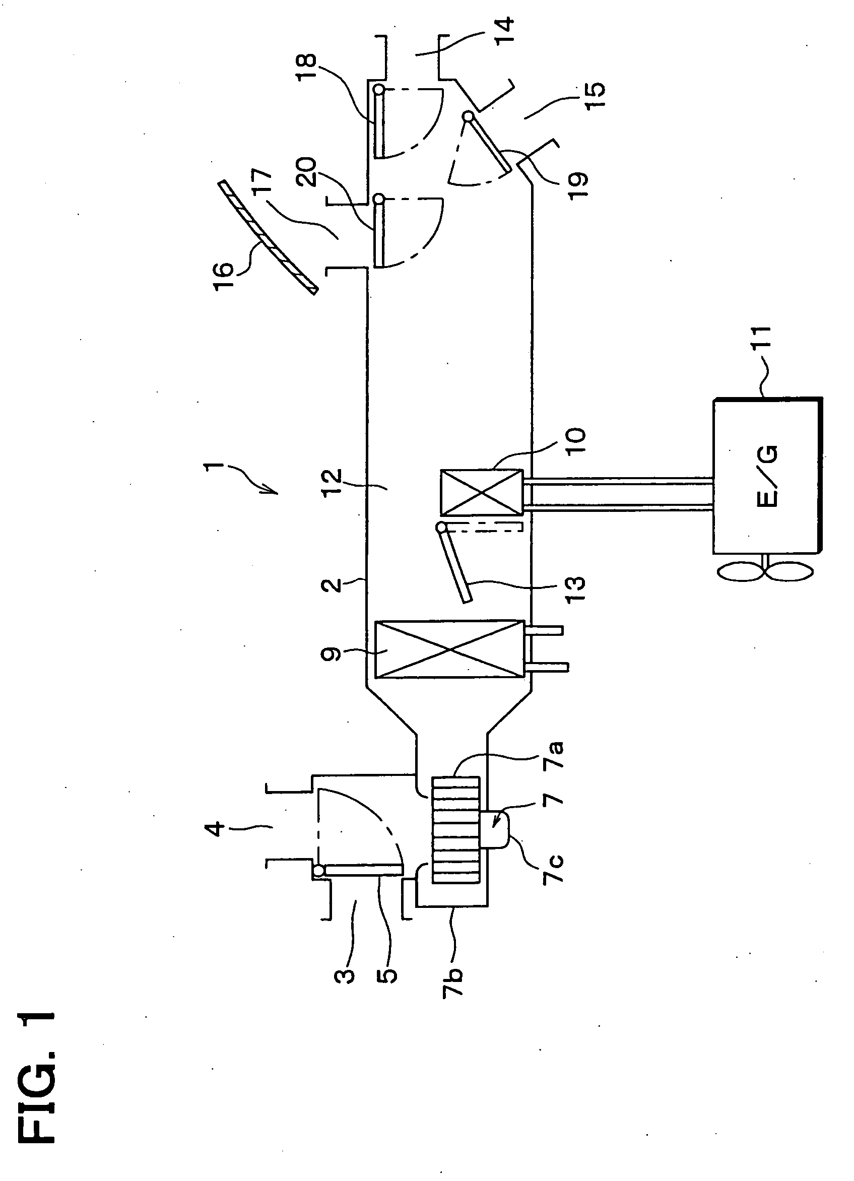
[0044] A multi-blade centrifugal blower 7 according to a first embodiment of the present invention is suitably used in, for example, an air conditioner 1 for a vehicle. FIG. 1 shows the air conditioner 1 having a water-cooled engine. An air conditioner casing 2 of the air conditioner 1 is provided with an inner-air suction port 3 through which air inside a passenger compartment of the vehicle is introduced into the air conditioner 1, an outer-air suction port 4 through which air outside the passenger compartment is introduced into the air conditioner 1, and a suction-port switching door 5 for selectively closing and opening the suction ports 3 and 4. The suction-port switching door 5, the suction ports 3 and 4 are disposed at an air upstream portion in an air passage defined by the air conditioner casing 2.

[0045] The multi-blade centrifugal blower 7 (blower 7) and a filter (not shown) for removing dust in air are arranged in the air conditioner casing 2 and disposed at an air downs...

second embodiment

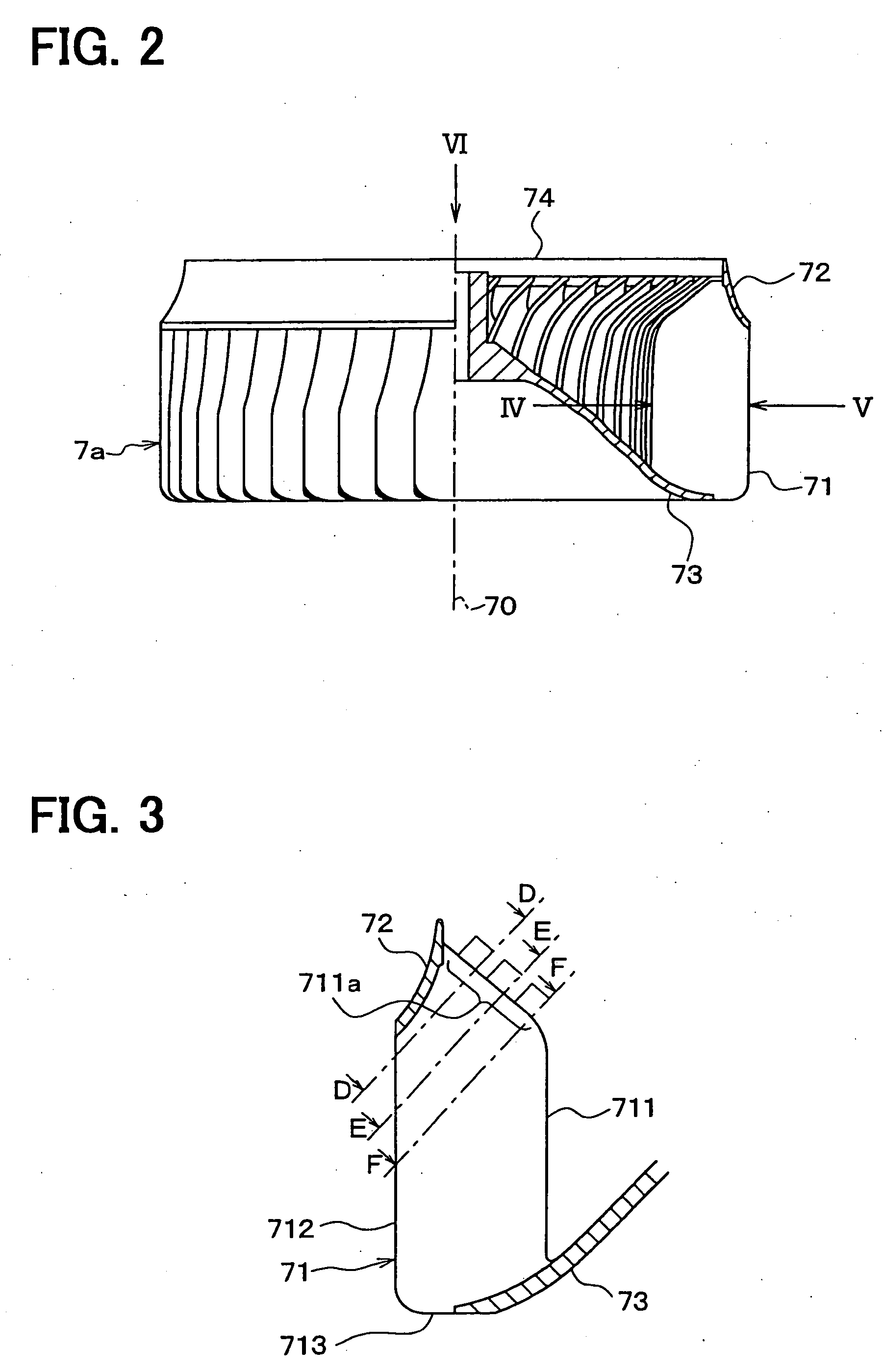
[0077] According to a second embodiment of the present invention, referring to FIG. 19, the taper portion 711a of the blade 71 has a substantial arc shape. Thus, a smooth curved surface can be readily provided for the blade 71.

third embodiment

[0078] According to a third embodiment of the present invention, referring to FIG. 20, the taper portion 711a extends to the whole inside periphery 711 of the blade 71. The taper portion can have a substantial arc shape, for example.

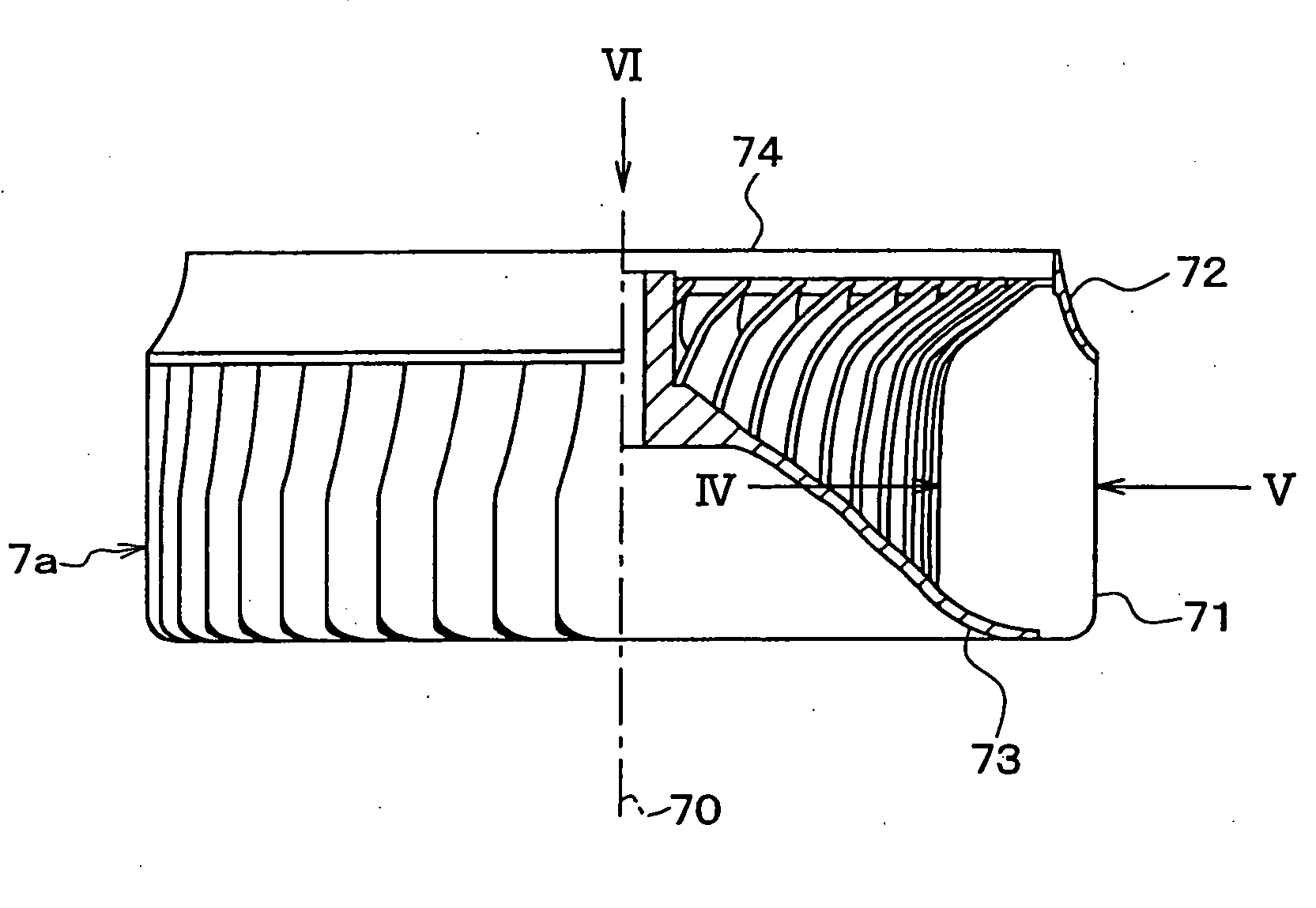
[0079] The taper portion 711a tapers from the other rotation-shaft-direction end side (i.e., opposite side to suction portion 74) of the taper portion 711a toward the one rotation-shaft-direction end side (i.e., side of suction portion 74) thereof. That is, the other rotation-shaft-direction end side of the taper portion 711a is positioned at the relatively inner side of the impeller wheel 7a, as compared with the one rotation-shaft-direction end side of the taper portion 711a.


PUM


Abstract

Each of blades of a multi-blade centrifugal blower is provided with a taper portion, which is arranged at an inside periphery at least at the side of one rotation-shaft-direction end of the blade and tapers from the side of other rotation-shaft-direction end of the blade toward the side of the one rotation-shaft-direction end. The taper portion is positioned at a rotation-direction front side with respect to a back portion disposed at the side of the other rotation-shaft-direction end of the blade. Each of inlet angles throughout the taper portion is set in a range from 55° to 74°. Therefore, air flowing speed at an outlet of an impeller wheel is uniformed throughout the blade width. Work capacity and efficiency of the impeller wheel are increased, while noise is reduced.

Description

CROSS REFERENCE TO RELATED APPLICATION [0001] This application is based on Japanese Patent Applications No. 2004-372912 filed on Dec. 24, 2004, and No. 2005-283598 filed on Sep. 29, 2005, the disclosure of which is incorporated herein by reference. FIELD OF THE INVENTION [0002] The present invention relates to a multi-blade centrifugal blower, which sucks air from a rotation-shaft-direction end side thereof and blows air toward a diameter-direction outer side thereof. BACKGROUND OF THE INVENTION [0003] A general multi-blade centrifugal blower is shown in FIG. 23. An impeller wheel 7a of the blower is accommodated in a casing 7b, and provided with multiple blades 71 which are arranged around the central line 70 of a rotation shaft (not shown) of the blower. The blower sucks air through a suction portion 74 disposed at the side of one rotation-shaft-direction end of the blower, and blows air toward a diameter-direction outer side of the blower. [0004] The impeller wheel 7a is provided...

Claims


Application Information

Patent Timeline
Patent Type & Authority Applications(United States)
IPC IPC(8): F04D29/44
CPCF04D29/282F04D29/30
Inventor OCHIAI, TOSHINORISAKAI, MASAHARUIMAHIGASHI, SHOICHIMITSUISHI, YASUSHI
Owner DENSO CORP
Why Eureka
Try Eureka