Active flow modifications on wind turbine blades

a technology of active flow and wind turbine blades, which is applied in the direction of propulsive elements, vessel construction, marine propulsion, etc., can solve the problems of large torque, which is the driving force imparted by the wind to the wind turbine, and the provision to stop the flow control, so as to improve the performance, reduce load, and the effect of large wind turbine blades

Active Publication Date: 2006-06-29
GENERAL ELECTRIC CO
View PDF17 Cites 60 Cited by
  • Summary
  • Abstract
  • Description
  • Claims
  • Application Information

AI Technical Summary

Benefits of technology

[0006] There exists a need for active separation control methods and systems that provide for an ability to manipulate lift production on demand, and blade design concepts that utilize such an ability to decrease system loads to enable higher performance wind turbines. Such active flow modification methods can additionally or alternatively be utilized for generally making the wind turbine more efficient and less noisy.
[0007] Embodiments of the present invention are directed toward improving wind turbine performance by using active flow modification for reducing loads, aerodynamic losses, aerodynamic noise, or combinations thereof.
[0009] Another aspect of the invention resides in a method of operating a wind turbine by obtaining a current state of at least one operating condition of the wind turbine and actively modifying the wind flow proximate to the blade in response to the current state to improve the performance.
[0010] Another aspect of the invention is a wind turbine blade design comprising the use of active flow modification devices on the wind turbine blade to reduce loads and enable a larger size of the wind turbine blade than would be within operating specifications without the active flow modification devices. In this application, a wind turbine would produce the required lift or maximized lift for power production with a smaller blade. Under hostile wind conditions, it would be turned off resulting in a reduction of system loads in those conditions. With such a means of addressing system load constraints, the wind turbine rotor can be grown to a larger size resulting in higher energy capture, while operating under the same load limitations as when the blade design does not include the use of a flow separation control system.
[0011] Another aspect of the invention is a wind turbine blade design comprising the use of active flow modification devices on a tip of the wind turbine blade to have lower aerodynamic losses and noise than would be within operating specifications without the active flow modification devices.
[0012] Another aspect of the invention is a wind turbine blade design that incorporates an active flow modification system that can be used to reduce the undesired loadings, either intermittent or sustained, caused by changing wind conditions (for example, by initiating separation and reducing lift) to provide improved performance.

Problems solved by technology

Of the many challenges that exist in harnessing wind energy, one is maximizing wind turbine performance while minimizing system loads in given wind conditions.
In general, flow separation over wind turbine blades leads to stall, which is often a limiting factor in wind turbine blade design.
When stall occurs, lift generated by the blade decreases significantly and a large component of the torque, which is the driving force imparted by the wind to the wind turbine, is lost.
Some passive flow control solutions, for example, vortex generators, have been applied to remedy the boundary layer separation problem, but in such solutions there is no provision to stop the flow control when the flow control becomes unnecessary or undesirable.
For example, one of the principal constraints in wind turbine design is that caused by system loads.
When a separation control solution is being used to enhance lift, the blade experiences higher loading that can reach failure-inducing levels if the wind conditions change beyond normal operational or expected levels.
The higher systems loads on a larger rotor (thicker and larger chord length) due to structural and material limitations, and blade / tower clearances typically constrain this growth.
Another challenge is posed by changing wind conditions such as wind gusts or storms that lead to an undesired loading of the wind turbine blade as the lift being generated fluctuates or increases to very large levels.
These loads constraints often lead to increased cost of the blade and other components of the wind turbine system, which can reduce or cancel the benefits of growing the rotor in terms of a system-level metric like cost of energy.
Another challenge that exists in harnessing wind energy relates to undesirable effects of the tip vortex generated by the wind flow at the tip of the blades.
Besides causing energy harnessing losses, these tip vortices also lead to undesirable noise emanating from the tip end of the blade.

Method used


Image

  • Active flow modifications on wind turbine blades
  • Active flow modifications on wind turbine blades
  • Active flow modifications on wind turbine blades

Examples


Embodiment Construction

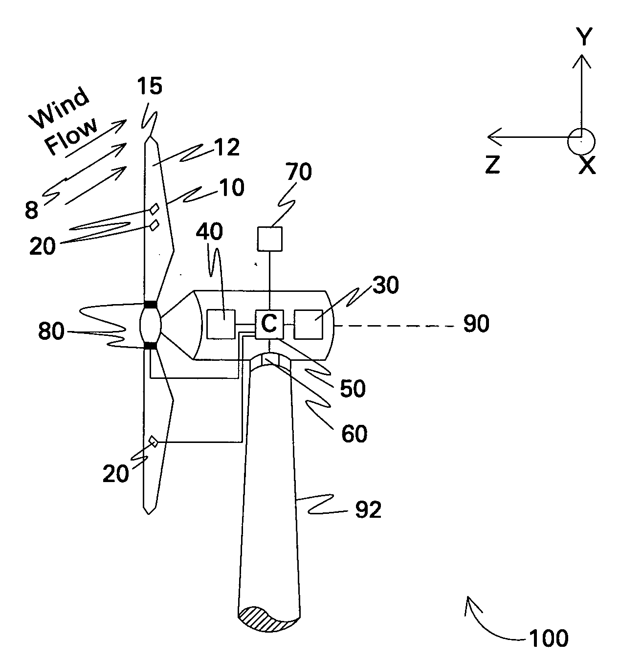
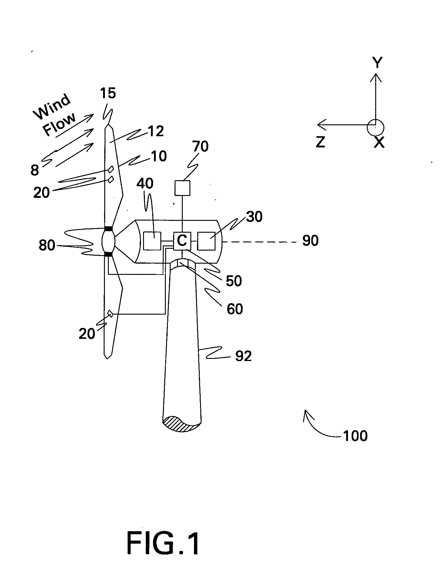
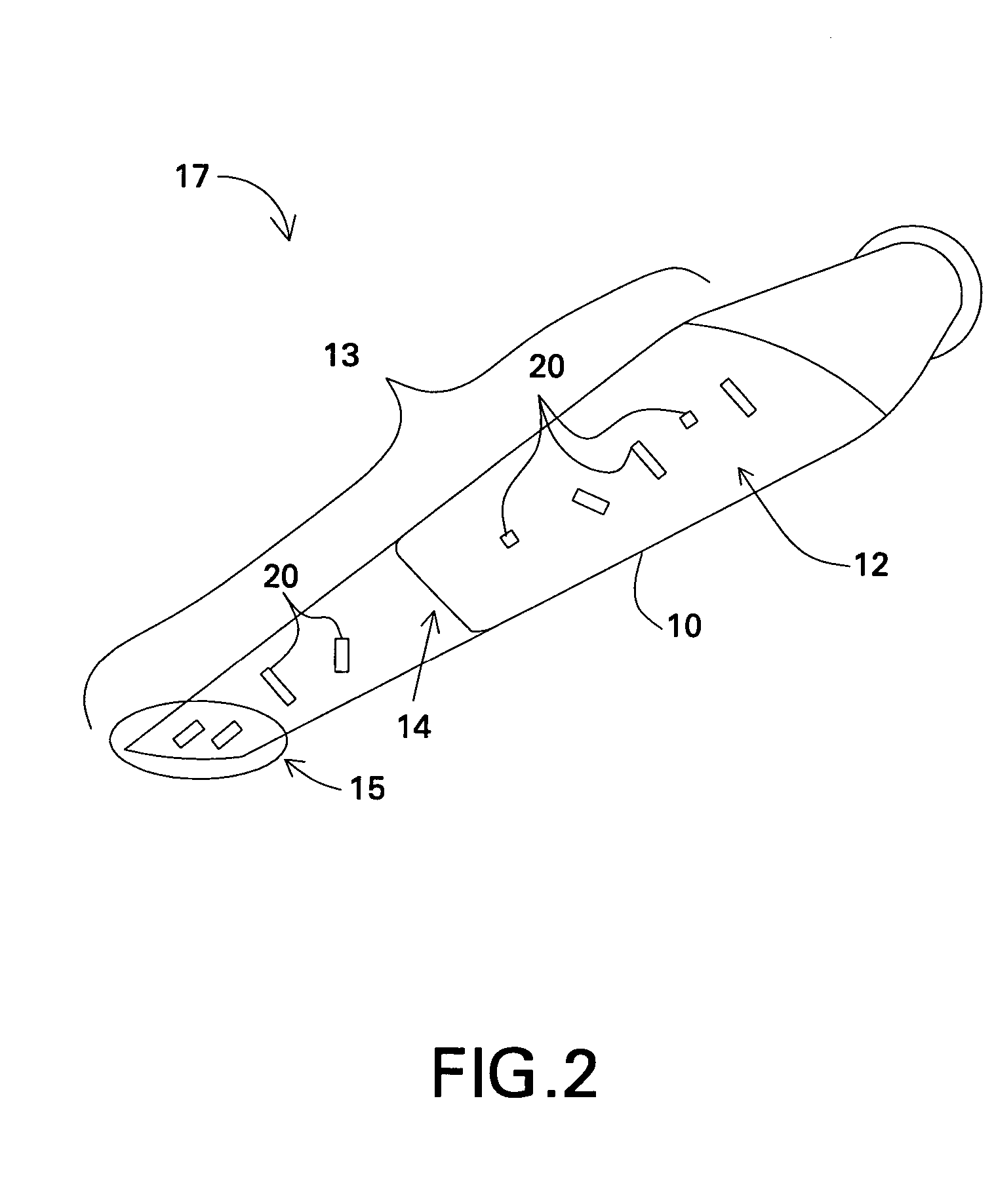
[0020]FIG. 1 illustrates a wind turbine 100 in accordance with one embodiment of the present invention. The wind turbine 100 includes a wind turbine blade 10 configured to rotate about an axis 90 upon impact of an incident wind flow, for example, a wind flow 8 as shown. It is appreciated that as used herein, the terms “a”, “an” and “the” refer to “at least one” and plural variants thereof, unless otherwise specifically mentioned or indicated by the context. The axis of rotation 90 is along the z-axis in the axes system of FIG. 1, and the plane of rotation of the blades 10 is x-y plane, the x-axis coming out of the plane of the paper. An active flow modification device 20 is further disposed on the blade 10, and the blade and the active flow modification device 20 together form a wind turbine blade assembly 17 (shown in FIG. 2). The active flow modification device 20 is configured to modify the wind flow 8 proximate to the blade, thereby modifying a load on the wind turbine. The term...


PUM


Abstract

A wind turbine blade is situated on a wind turbine and includes a side and a tip. The blade is configured to rotate about an axis upon an impact of a wind flow on the blade. An active flow modification device is disposed on the blade. The active flow modification device is configured to receive active flow instructions and to modify the wind flow proximate to the blade. The resulting wind turbine blade uses these active flow modifications to achieve reduced loads, reduced aerodynamic losses, reduced noise, enhanced energy capture, or combinations thereof.

Description

BACKGROUND [0001] The invention relates generally to the field of wind turbines, and more specifically to active flow modification in wind turbines for reducing loads, reducing aerodynamic losses, improving energy capture, reducing noise, and combinations thereof. [0002] Wind turbines are increasingly gaining importance in the area of renewable sources of energy generation. In recent times, wind turbine technology has been applied to large-scale power generation applications. Of the many challenges that exist in harnessing wind energy, one is maximizing wind turbine performance while minimizing system loads in given wind conditions. Non-limiting examples of improved wind turbine performance parameters, which lead to minimized cost of energy, include maximized aerodynamic efficiency, maximized energy output, minimized wind turbine system loads, minimized noise, and combinations thereof. Examples of wind turbine system loads include extreme loads (operational and parked / idling) and fa...

Claims


Application Information

Patent Timeline
Patent Type & Authority Applications(United States)
IPC IPC(8): B64C27/615
CPCF03D1/0608F05B2240/31Y02E10/721Y02E10/722Y02E10/723Y10S415/914Y02E10/72
Inventor SADDOUGHI, SEYED GHOLAMALIGUPTA, ANURAGGIGUERE, PHILIPPE
Owner GENERAL ELECTRIC CO
Why Eureka
Try Eureka