Tube for transporting fluid

a technology for transporting fluids and tubes, applied in the direction of coupling devices, two-part coupling devices, electrical devices, etc., can solve the problems of increasing the number of required parts, increasing the cost of connecting the tubes, and reducing the service life of the tubes, so as to achieve the effect of simple structur

Inactive Publication Date: 2006-06-29
SUMITOMO RIKO CO LTD
View PDF15 Cites 2 Cited by
  • Summary
  • Abstract
  • Description
  • Claims
  • Application Information

AI Technical Summary

Benefits of technology

[0038] As stated above, according to the present invention, the tube for transporting a fluid is provided with a quick connector on a tube end portion, for example, integrally or in unitary relation. The quick connector comprises the tubular connector housing, for example, in a form of the tube end portion of diametrically enlarged shape, the seal ring incorporated in the connector housing, and the retainer portion having the retainer tubular portion, for example, in a form of the leading end portion of the connector housing and the engaging recessed portion formed in the retainer tubular portion. According to the present invention, number of parts required for connecting the tube for transporting a fluid with the mating pipe may be decreased, and procedure or labor for attaching the separate quick connector to the tube may be omitted, and thereby a man-hour required for connecting the tube to the mating pipe may be decreased. So, totally, required cost may be largely reduced.
[0041] In this manner, the engaging recessed portion in which the engaging projection of the mating pipe is fitted in engaging relation may be fabricated in a very simple structure.

Problems solved by technology

However, in case of conventional connecting structure using this quick connector 206, as the quick connector 206 is provided separately for connecting the mating pipe 202 with the tube 200, number of required parts is increased, and this inevitably leads to increase of required cost.
And, this entails a problem that a number of man-hour is required for assembling work relative to the tube 200 including press-fitting work of the quick connector 206 in the tube 200, specifically press-fitting work of the nipple portion 210 in the tube 200, connecting procedure of the tube 200 becomes bothersome, and cost for connecting the tube 200 to the mating pipe 202 is increased.
In this construction, there is not only a problem that the elastic member of shape intended for a seal and a stopper is required, but also a problem that it is difficult to secure a high bonding force between the tube and the mating pipe in an axial direction.

Method used


Image

  • Tube for transporting fluid
  • Tube for transporting fluid
  • Tube for transporting fluid

Examples


Embodiment Construction

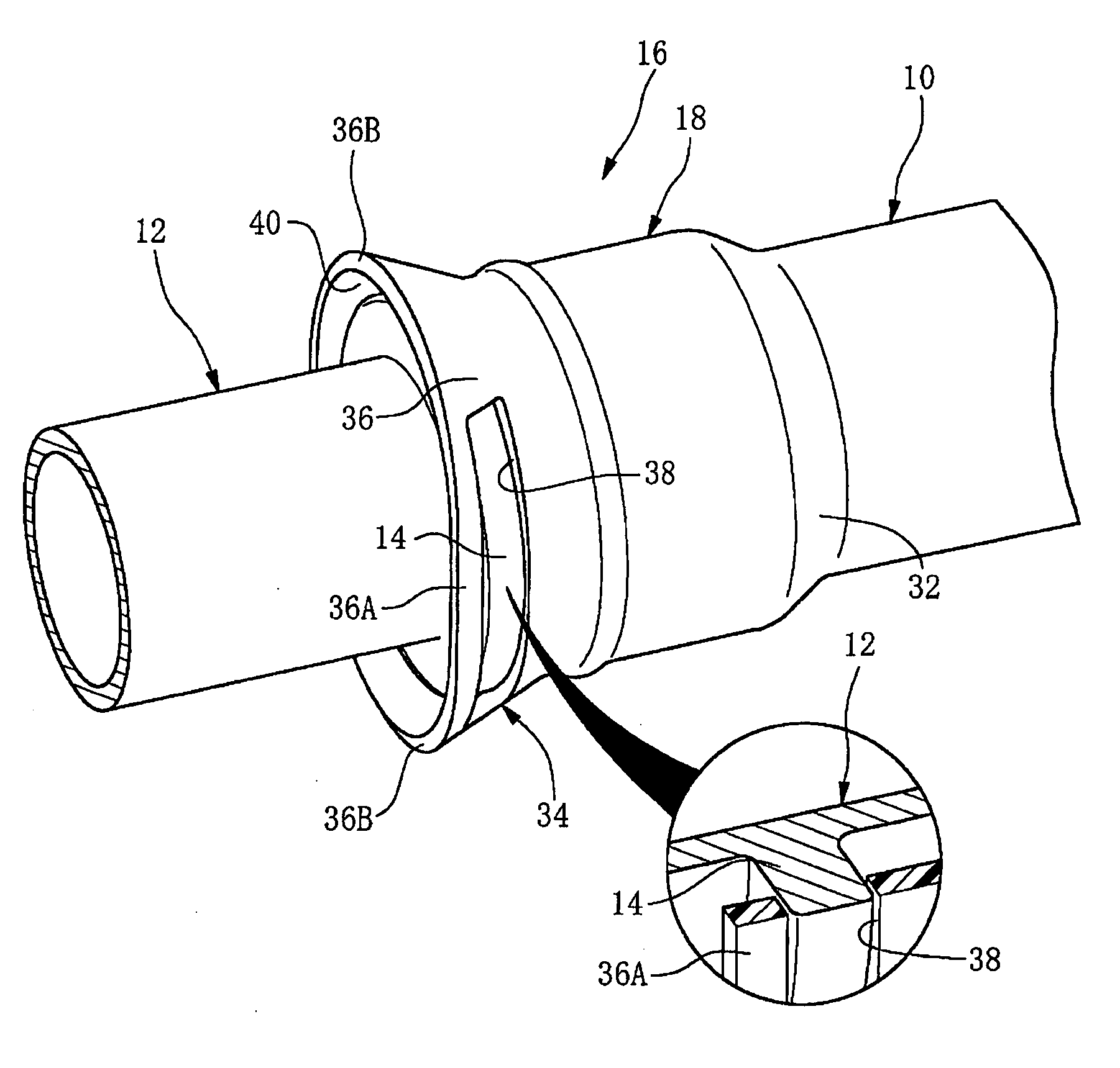
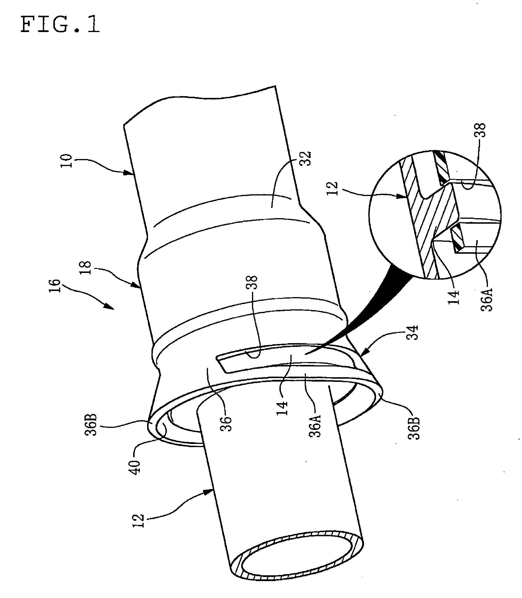
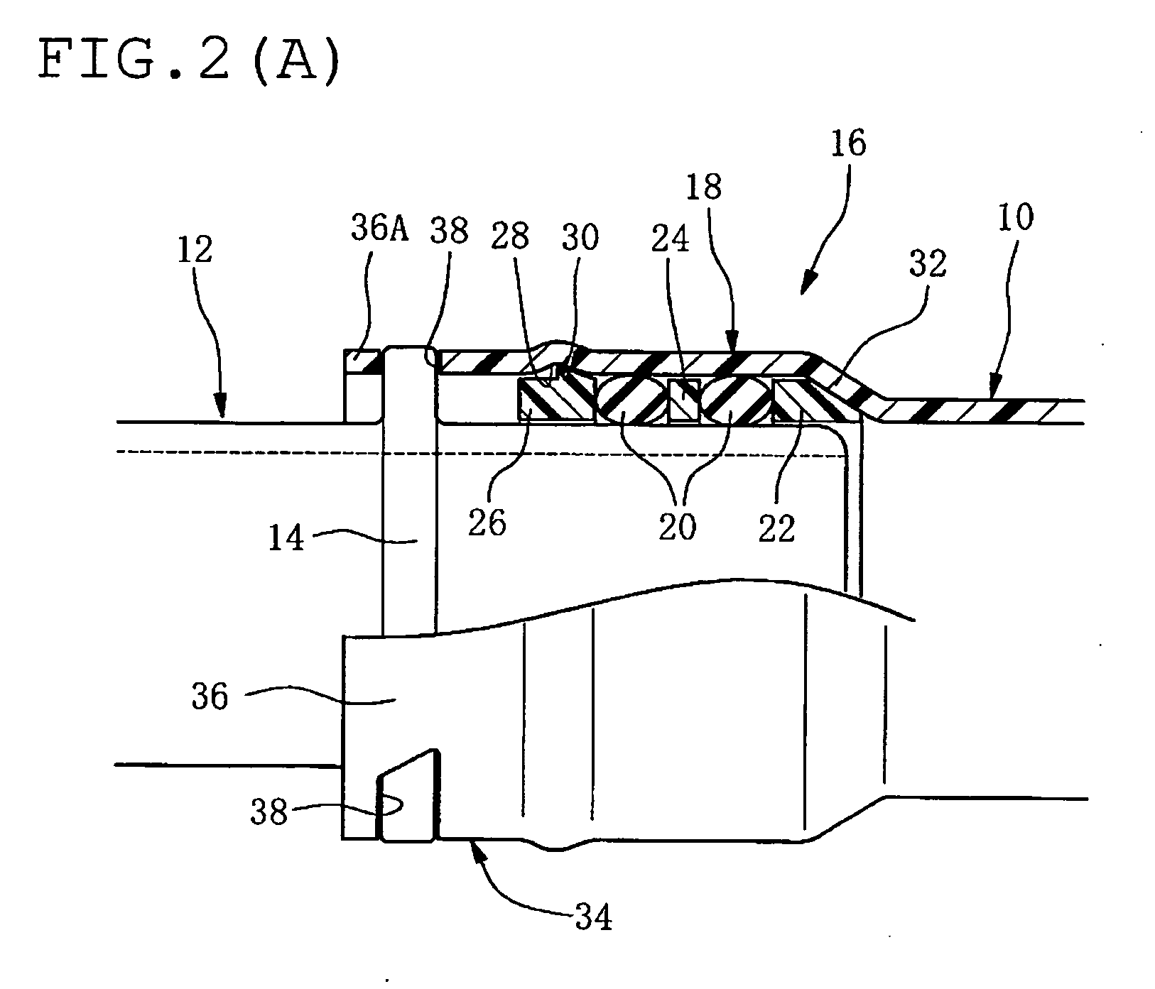
[0066] In FIGS. 1 and 2, reference numeral 10 indicates a hard tube (here, made of resin) for transporting a fluid, and reference numeral 12 indicates a hard mating pipe with which the tube 10 is connected.

[0067] The mating pipe 12 is formed integrally with an engaging projection 14 that projects annularly from an outer peripheral surface of the mating pipe 12.

[0068] In this preferred embodiment, the tube 10 is provided integrally with a quick connector 16 on an end portion thereof.

[0069] Meanwhile, the tube 10 is configured to have a flexural modulus in a range of 300 MPa to 2500 MPa on an end portion thereof. And, the tube 10 may have a multilayered construction as follows. For example, the layers are is bonded each other by means of an adhesive agent (adhesive layer).

[0070] 1) An inner layer made of ethylene-tetrafluoroethylene copolymer (ETFE) and an outer layer made of nylon 12 (PA12).

[0071] 2) An electrically conductive inner layer made of ETFE, a middle layer made of ETF...


PUM


Abstract

A tube for transporting a fluid is provided integrally with a quick connector on a tube end portion. The quick connector has a tubular connector housing defined by the tube end portion in a form of diametrically enlarged shape, an O-ring contacting with an outer peripheral surface of a mating pipe to provide a seal, and a retainer portion. The retainer portion has a retainer tubular portion defined by a leading end portion of the connector housing and an engaging recessed portion. The engaging recessed portion allows an engaging projection of the mating pipe to fit in the engaging recessed portion resiliently or under a resilient force from an inner side toward a radially outward direction in a mutually engaging relation.

Description

BACKGROUND OF THE INVENTION [0001] 1. Field of the Invention [0002] The present invention relates to a tube for transporting a fluid, specifically, the one provided with a means for connecting the tube for transporting a fluid with a mating pipe. [0003] 2. Description of the Related Art [0004] Previously, a hard resin tube has been widely used for transporting various fluids. For connecting the resin tube with a mating pipe, used is a quick connector that is constructed separately therefrom. [0005] Such type of a quick connector is disclosed, for example, in Patent Document 1 below. [0006]FIGS. 9 and 10 show a concrete example of construction of this quick connector. [0007] In FIGS. 9 and 10, reference numeral 200 indicates a tube, and reference numeral 202 is a mating pipe to which the tube 200 is to be connected. [0008] The mating pipe 202 is formed with an annular bulge portion (engaging projecting portion) 204 bulging radially outward on an outer peripheral surface thereof. [000...

Claims


Application Information

Patent Timeline
Patent Type & Authority Applications(United States)
IPC IPC(8): H01R24/00
CPCF16L37/084
Inventor MIYAJIMA, ATSUOSHIMIZU, KOJI
Owner SUMITOMO RIKO CO LTD
Why Eureka
Try Eureka