
Wireless system for providing instrument and implant data to a surgical navigation unit

Inactive Publication Date: 2006-06-29
STRYKER CORP
View PDF8 Cites 481 Cited by
  • Summary
  • Abstract
  • Description
  • Claims
  • Application Information

AI Technical Summary

Benefits of technology

[0011] This invention is related to a new and useful surgical navigation system. The system of this invention includes a tracker and surgical components that are integrated together. The tracker and complementary components are integrated so that the tracker, upon attachment to a component, reads the data in a memory integral with the component. The data in the memory include information that describes the characteristics of the component. The tracker broadcasts the read data wirelessly to the static components of the system. The system, based on these data, the location of the tracker and the previously stored data, provides information that accurately describes the location of the component at the surgical site.

Problems solved by technology

Nevertheless, there are times where it is difficult to provide a corded connection to the instruments, implants and other components applied to a surgical site.
Attaching a cord to each of these components as part of surgical procedure to read their RFIDs can complicate and increase the time it takes to perform the procedure.
Requiring the personnel to take this step increases the complexity of the procedure and overall time it takes for the procedure to be performed.
Moreover, in the event the steps are not taken to properly perform the identification procedure, the navigation system may provide incorrect information about the location or shape of the surgical component.
This type of error may occur, for example, when a surgeon is using a number of different trial implants to determine the proper size or type of implant that should properly be fitted to the patient.
If, after the switching of the attached trial implant, the component identification step is not performed, the surgical navigation system may generate information that gives an inaccurate impression of the implant.

Method used


Image

  • Wireless system for providing instrument and implant data to a surgical navigation unit
  • Wireless system for providing instrument and implant data to a surgical navigation unit
  • Wireless system for providing instrument and implant data to a surgical navigation unit

Examples


Embodiment Construction

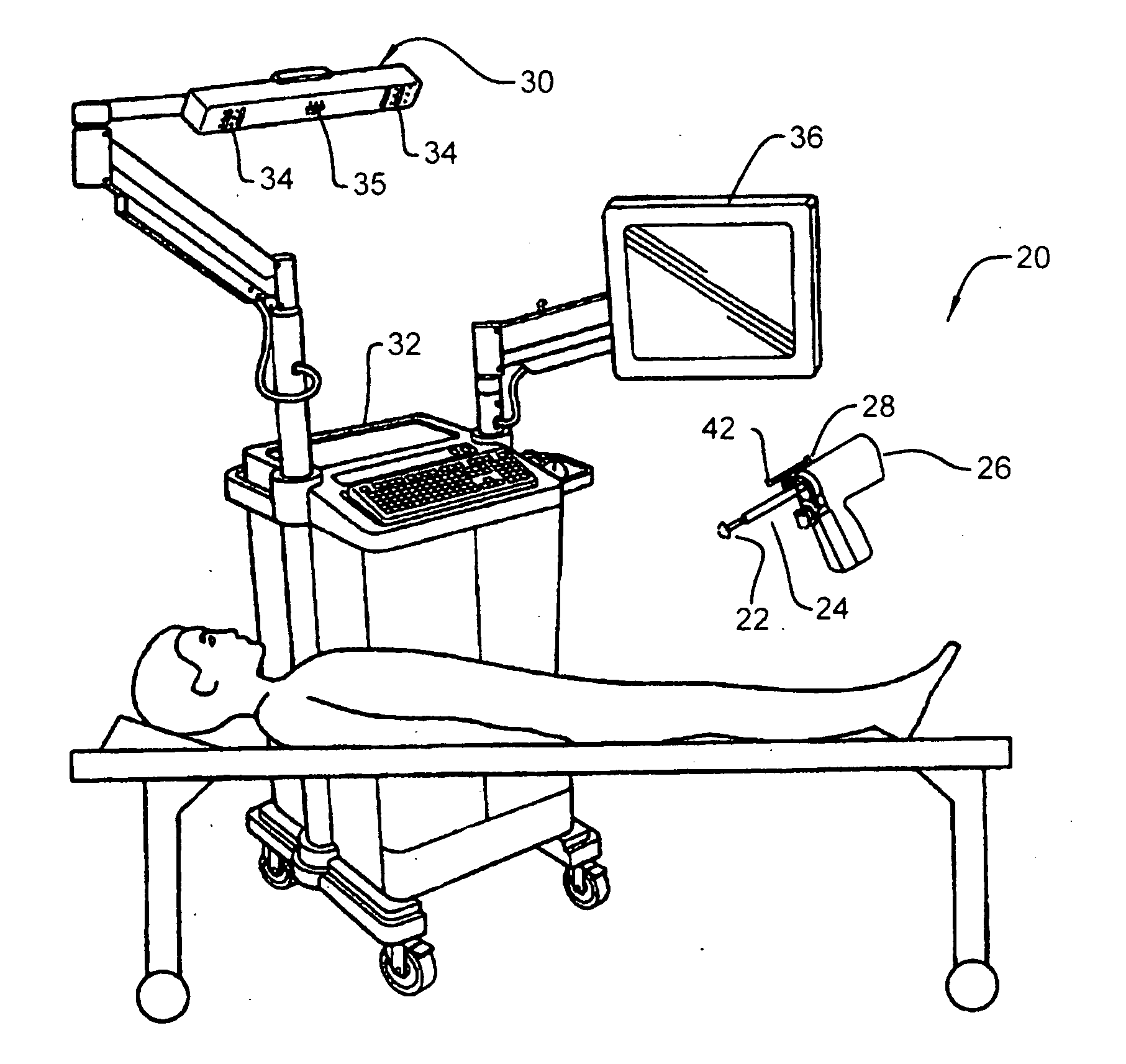
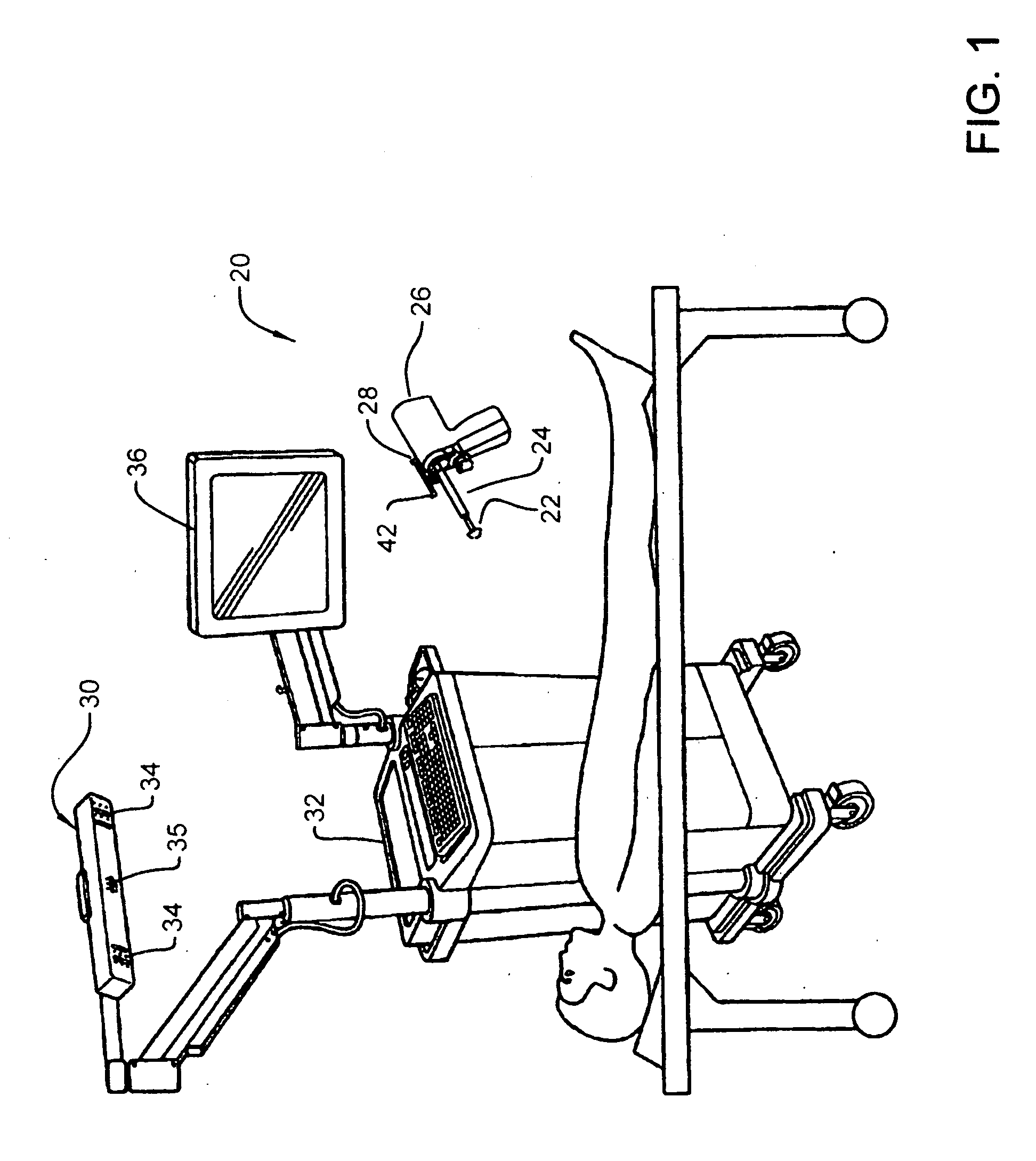
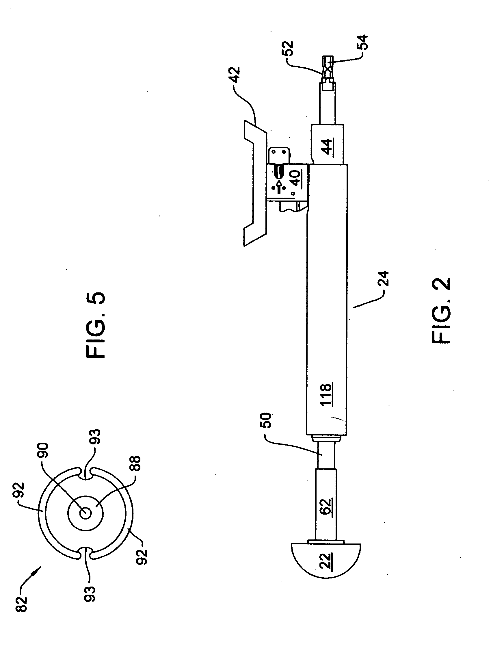
[0048]FIG. 1 depicts a surgical navigation system 20 of this invention that obtains data about surgical components 22 and 24 without wire connections to the components. In FIG. 1, surgical component 22 is a reamer. Surgical component 24 is a handle assembly. The proximal end of the handle assembly 24 is attached to a battery operated driver 26 that actuates the reamer 22. (“Proximal”, it is understood, means away from the surgical site. “Distal” means towards the surgical site.) Not shown and not part of the invention is the battery attached to the base of the handgrip of the driver 26 that supplies the energization current for the driver. It should also be understood, and as will be discussed below “surgical component” may be any other instrument used to cut, form or shape tissue, a trial implant or an actual implant. Sometimes, the surgical component is alternatively referred to as a “surgical implement.”

[0049] System 20 of this invention includes a tracker 28 attached to handle a...


PUM


Abstract

A system for wirelessly providing data regarding surgical implements such as surgical tools, trial and inserts themselves to a surgical navigation unit. Each implement includes an RFID in which data regarding the implement are stored. The tool used to fit the implement has a first coil positioned to exchange signals with a complementary coil integral with the RFID. The tool also has a prism for receiving a navigation tracker. A second tool coil, in the prism, is connected to the first coil. The second tool coil is also connected to an RFID integral with the tool. The tracker, through the tool coils, reads the data in the implement RFID and the tool RFID. A transmitter in the tracker wirelessly forwards the data to the surgical navigation system. The data are used to facilitate reactive workflow guidance of the procedure and monitor the position of the implement.

Description

RELATIONSHIP TO EARLIER FILED APPLICATION [0001] This application claims priority from U.S. Provisional Patent Application No. 60 / 634,588 filed Dec. 9, 2004 the contents of which are incorporate herein by reference.FIELD OF THE INVENTION [0002] This invention is generally directed to a surgical navigation system. More particularly, this invention is directed to a system for providing a surgical navigation system with information about the surgical instruments, surgical devices and implants tracked by the system without wired connections to the instruments, devices and implants. BACKGROUND OF THE INVENTION [0003] Surgical navigation systems have become extremely useful tools in operating rooms. Generally, a surgical navigation system consists of one or more trackers. Each tracker is attached to a specific surgical instrument, device or implant. The system also includes a localizer. Each tracker generates one or more specific signals. These signals may be radio signals, other EM signa...

Claims


Application Information

Patent Timeline
IPC IPC(8): A61B5/05
CPCA61B17/1626A61B17/1666A61B17/32002A61B19/44A61B19/50A61B19/52A61B19/5244A61B19/54A61B2017/00455A61B2019/448A61B2019/501A61B2019/502A61B2019/508A61B2019/5229A61B2019/5251A61B2019/5255A61B2019/5274A61B2019/5416A61B2019/5483A61B2019/5487A61F2/34A61F2/36A61F2/3662A61F2/367A61F2/4607A61F2/4609A61F2002/30601A61F2002/30841A61F2002/30894A61F2002/3625A61F2002/4629A61F2002/4632A61F2002/4681A61F2002/4628A61B2090/3983A61B2034/101A61B2034/102A61B90/36A61B2034/2055A61B2034/2074A61B2090/3916A61B34/20A61B90/90A61B90/98A61B34/10A61B2034/108A61B2090/372A61B2034/2051A61B90/39A61B2090/3987
Inventor MALACKOWSKI, DONLAVIGNA, NICHOLAS
Owner STRYKER CORP
Learn More