Bi-directional steerable catheter control handle

a control handle and directional steering technology, applied in the field of control handles, can solve the problems of insufficient ability of control handles, inability to precisely operate them by a single hand, and large volume of control handles, and achieve the effect of preventing the rotational displacement of the first member

Active Publication Date: 2006-06-29
ST JUDE MEDICAL ATRIAL FIBRILLATION DIV
View PDF99 Cites 212 Cited by
  • Summary
  • Abstract
  • Description
  • Claims
  • Application Information

AI Technical Summary

Benefits of technology

[0017] In one embodiment, where the wire guide has a generally circular latitudinal cross-section, the wire guide has a first feature for engaging a second feature of the first member, thereby preventing the rotational displacement of the first member about the wire guide. In one embodiment, the first feature is a groove and the second feature is a key for being slideably received in the groove.

Problems solved by technology

Prior art control handles for controlling distal end deflection of catheter bodies have several drawbacks that adversely impact the handles' ability to be operated precisely by a single hand.
First, the control handles are often excessively bulky.
Second, the control handles are often inadequate with respect to their ability to provide finely controlled deflection adjustment for the distal end of the catheter body.
Third, the control handles often provide inadequate deflection wire travel for a desired medical procedure.
Fourth, the control handles often have a mechanical advantage that is less than desirable and, as a result, require significant effort to operate on the part of a user.
Sixth, the wire displacement mechanisms within the control handles have a tendency to permanently deform the deflection wires.
Seventh, the wire displacement mechanisms within the control handles typically make it difficult, if not impossible, to provide a lumen that runs uninterrupted from the proximal end of the control handle to the distal end of the catheter body.

Method used


Image

  • Bi-directional steerable catheter control handle
  • Bi-directional steerable catheter control handle
  • Bi-directional steerable catheter control handle

Examples


Embodiment Construction

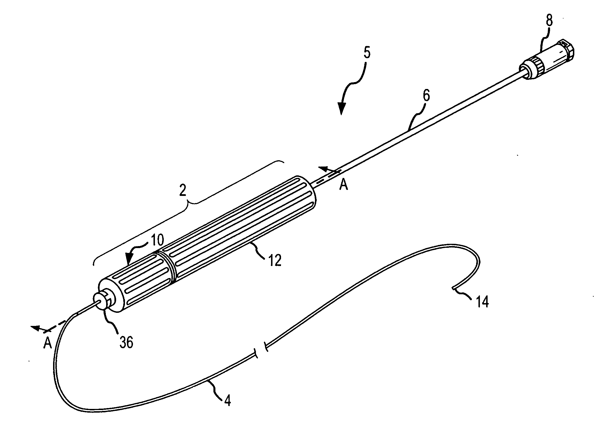
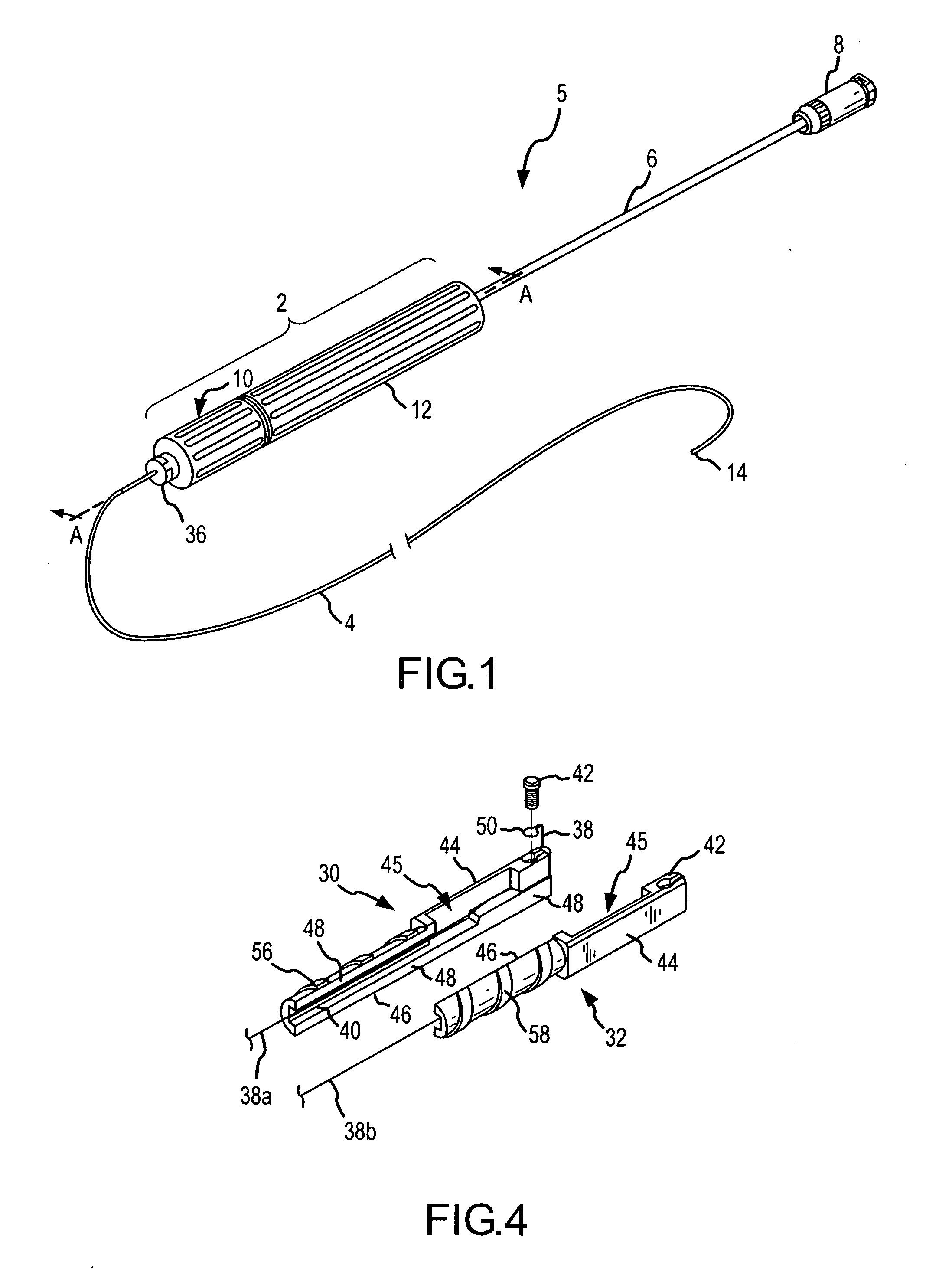
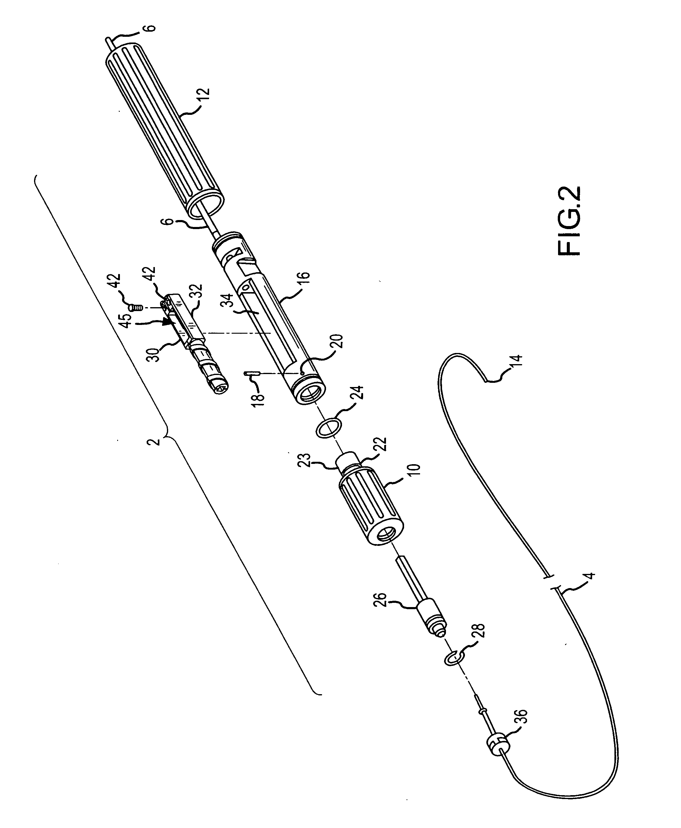
[0061]FIG. 1 is an isometric view of one embodiment of the present invention, which is a control handle 2 for a flexible tubular body 4 of a catheter 5. Throughout this specification, the term catheter is meant to include, without limitation, catheters, sheaths and similar medical devices. As shown in FIG. 1, in one embodiment, the distal end of the handle 2 is connected to the catheter body 4 and the proximal end of the handle 2 is connected to tubing 6 that contains electrical wire and extends to an electrical connector 8. The handle 2 includes an adjusting knob 10 and a handle grip 12. As will become clear from this specification, the handle 2 of the present invention is advantageous in that it is compact and allows a user to manipulate the catheter body's extreme distal end 14 in a bi-directional manner by pivoting the adjusting knob 10 relative to the handle grip 12 in one direction or the other about the longitudinal axis of the handle 2. Furthermore, in one embodiment, the ha...


PUM


Abstract

The present invention is a handle for controlling the deflection of a distal end of a catheter body. The catheter body includes first and second deflection wires that extend through the catheter body from the distal end of the catheter body. The handle comprises a slide base, an adjustment knob, a first slide and a second slide. The slide base includes a first end, a second end, and a slide compartment longitudinally extending through at least a portion of the slide base. The adjustment knob is rotateably connected to the first end of the slide base and includes a hole extending through the knob, wherein at least a portion of an inner diameter of the hole includes an internal right thread and an internal left thread. The first slide is located in the slide compartment, is adapted to be coupled to the first deflection wire, and includes an external right thread. The second slide is located in the slide compartment, is adapted to be coupled to the second deflection wire, and includes an external left thread. The internal threads of the knob engage the threads of the slides. Consequently, in operation, rotation of the adjustment knob causes the slides to displace in opposite directions within the slide compartment and the distal end of the catheter body to deflect accordingly.

Description

FIELD OF THE INVENTION [0001] The present invention relates to catheters and sheaths and methods of using catheters and sheaths. More particularly, the present invention relates to control handles for steerable catheters and sheaths and methods of manufacturing and using such handles. BACKGROUND OF THE INVENTION [0002] Catheters (i.e., catheters or sheaths) that have flexible tubular bodies with deflectable distal ends and control handles for controlling distal end deflection are used for many noninvasive medical procedures. For example, catheters having conductive electrodes along the distal ends of their bodies are commonly used for intra-cardiac electrophysiology studies. The distal end of a catheter body is typically placed into a patient's heart to monitor and / or record the intra-cardiac electrical signals during electrophysiology studies or during intra-cardiac mapping. The orientation or configuration of the distal end is controlled via an actuator located on the catheter's c...

Claims


Application Information

Patent Timeline
Patent Type & Authority Applications(United States)
IPC IPC(8): A61M31/00
CPCA61M25/0136A61M25/0147A61B5/042A61B5/287
Inventor BEDNAREK, MICHAEL C.WILKOWSKE, ERIC J.STEHR, RICHARD E.BUTLER, WILLIAM EMERSON
Owner ST JUDE MEDICAL ATRIAL FIBRILLATION DIV
Why Eureka
Try Eureka