
Communication system and transfer device

a communication system and transfer device technology, applied in the field of communication system and transfer device, can solve the problems of restricted access to the information transmitting-side network and the information providing-side network, and achieve the effects of low cost, high security, and efficient construction

Inactive Publication Date: 2006-06-29
NTT DOCOMO INC
View PDF3 Cites 45 Cited by
  • Summary
  • Abstract
  • Description
  • Claims
  • Application Information

AI Technical Summary

Benefits of technology

[0008] Therefore, it is unnecessary to construct a network connecting both the information transmitter and the information providing unit and having a unified security policy. Accordingly, a group of the information transmitter and the information transmitting-side network, and a group of the information providing unit and the information providing-side network, may connect via the transfer unit, while maintaining their own unique security policies, respectively. In addition, the transfer unit determines whether or not transmitting-side data and providing-side data are data that have been transmitted from the information transmitter and the information providing unit, respectively, and transfers data based on the determination results. Accordingly, between the group of the information transmitter and the transmitting-side network and the group of the information providing unit and the providing-side network, only specific data that has been transmitted from the information transmitter or the information providing unit is transmitted. Furthermore, access to the information providing-side network and the information transmitting-side network is restricted, respectively. As a result, the communication system may ensure high security.
[0009] Since it is unnecessary to construct a network connecting both the information transmitter and the information providing unit and having a unified security policy, the communication system can be construct

Problems solved by technology

Furthermore, access to the information providing-side network and the information transmitting-side network is restricted, respectively.

Method used


Image

  • Communication system and transfer device
  • Communication system and transfer device
  • Communication system and transfer device

Examples


first embodiment

(Communication System)

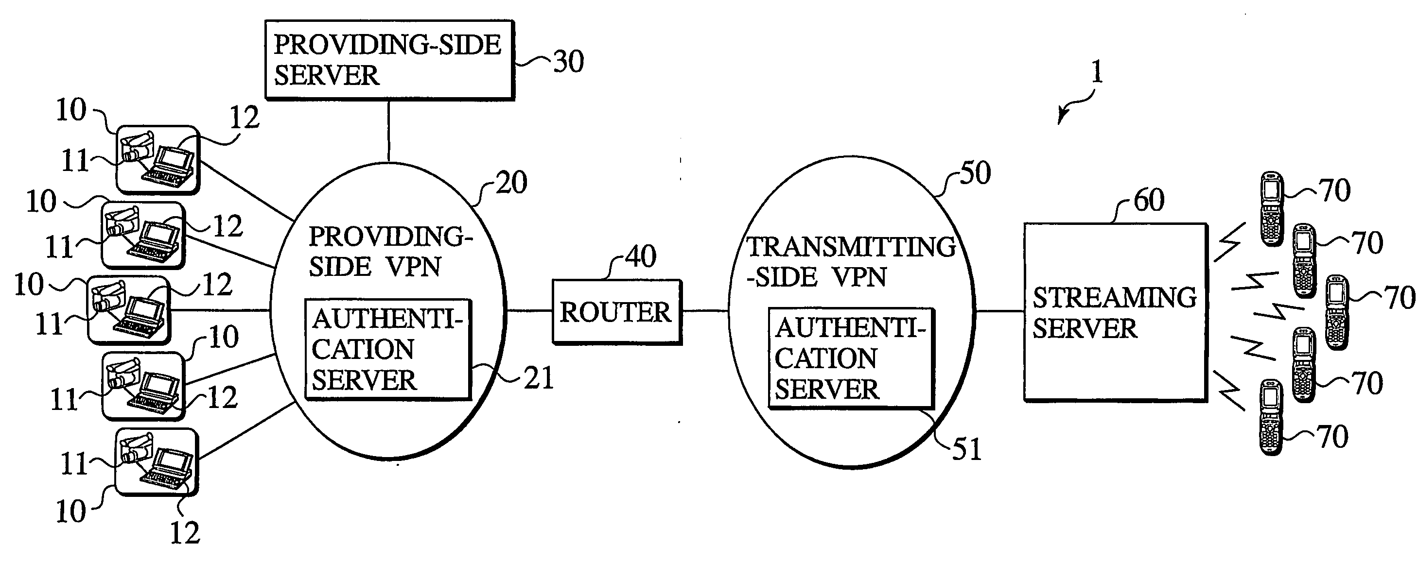
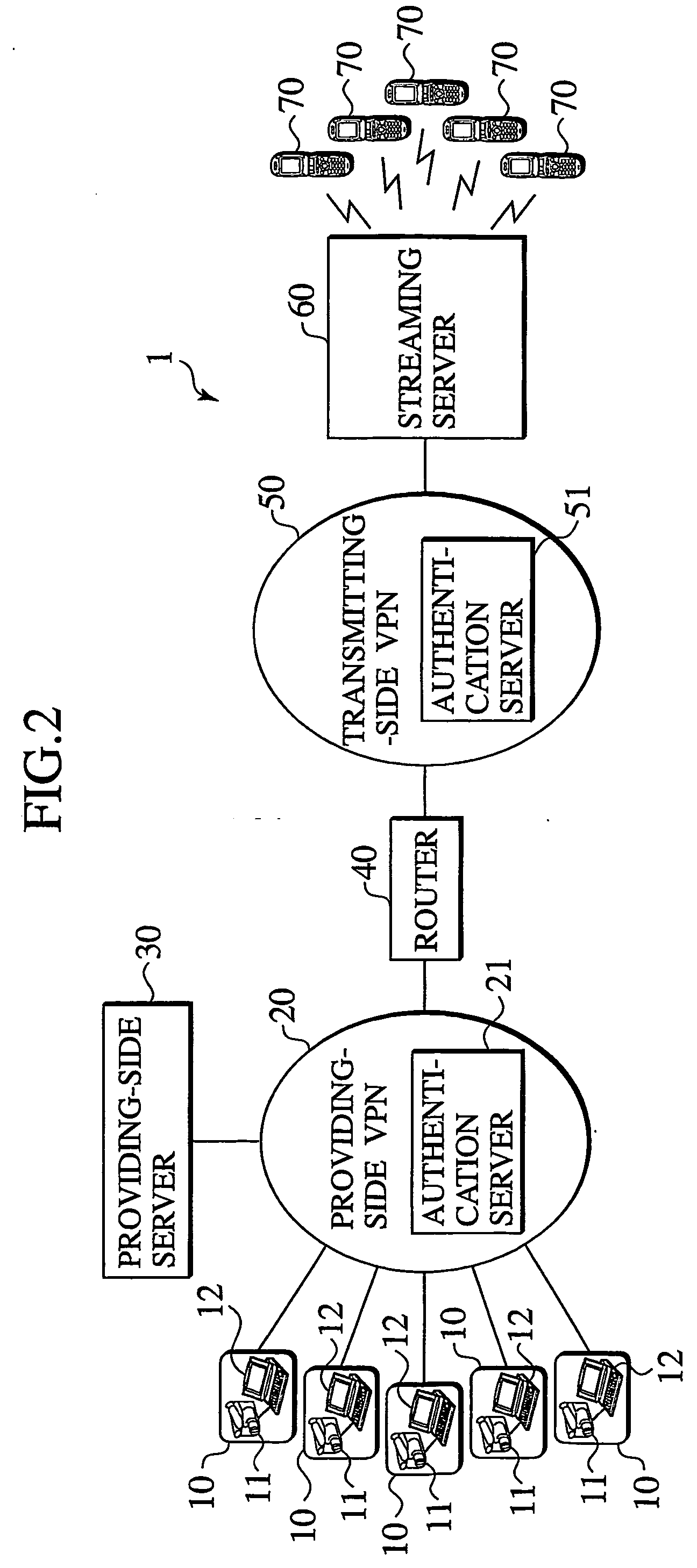
[0028] As shown in FIG. 2, a communication system 1 comprises a plurality of video data providing units 10, a providing-side VPN 20, a providing-side server 30, a router 40, a transmitting-side VPN 50, a streaming server 60, and a plurality of mobile terminals 70.

[0029] The video data providing units 10 are information providing units, which provide information data. The video data providing units 10 provide video data as information data. Each of the video data providing units 10 provides video data only to mobile terminals 70 used by users who are allowed to receive video data, from an information provider who provides information data such as video data. Note that in order to receive video data, a user of a mobile terminal 70 must be allowed to receive video data from an information provider, and obtain a user ID, a unique caller ID for the mobile terminal 70, or a password.

[0030] Each of the video data providing units 10 comprises a camera 11 and a vide...

second embodiment

[0072] Next, a second embodiment of the present invention is described. As shown in FIG. 8, a communication system 201 comprises a plurality of video data providing units (A) 10a, a providing-side VPN (A) 20a, a providing-side server (A) 30a, a plurality of video data providing units (B) 10b, a providing-side VPN (B) 20b, a providing-side server (B) 30b, a router 40, a transmitting-side VPN 50, a streaming server 260, a plurality of mobile terminals (A) 70a, and a plurality of mobile terminals (a) 70b. The transmitting-side VPN 50 is the same as the transmitting-side VPN 50 shown in FIG. 2.

[0073] The video data providing units (A) 10a comprises a camera (A) 11a and a video data providing server (A) 12a. The video data providing units (A) 10a connect to the providing-side VPN (A) 20a. Each of the video data providing units (A) 10a then transmits video data to the streaming server 260 via the providing-side VPN (A) 20a, the router 240, and the transmitting-side VPN 50. The video data...

third embodiment

[0104] As shown in FIG. 10, a communication system 301 comprises a plurality of video data providing units 10, a providing-side asynchronous transfer mode (ATM) network 320, a providing-side server 30, a router 340, a transmitting-side ATM network 350, a streaming server 60, and a plurality of mobile terminals 70. The video data providing units 10, the providing-side server 30, the streaming server 60, and the mobile terminals 70 are substantially the same as the video data providing units 10, the providing-side server 30, the streaming server 60, and the mobile terminals 70 shown in FIG. 2.

[0105] The providing-side ATM network 320 is an information providing-side network connecting the video data providing units 10 and being restricted access. The providing-side ATM network 320 connects to the router 340, and connects to the transmitting-side ATM network 350 via the router 340. The providing-side ATM network 320 comprises an authentication server 321. For the video data providing ...


PUM


Abstract

A video data providing unit (10) connects to a restricted access providing-side VPN (20). A streaming server (60) connects to a restricted access transmitting-side VPN (50). A router (40) determines whether or not transmitting-side data such as request data or instruction data received via the transmitting-side VPN (50) is data that has been transmitted from the streaming server (60), and whether or not providing-side data such as video data received via the providing-side VPN (20) is data that has been transmitted from the information providing unit (10). The router 40 then transfers the transmitting-side data and providing-side data based on those determination results.

Description

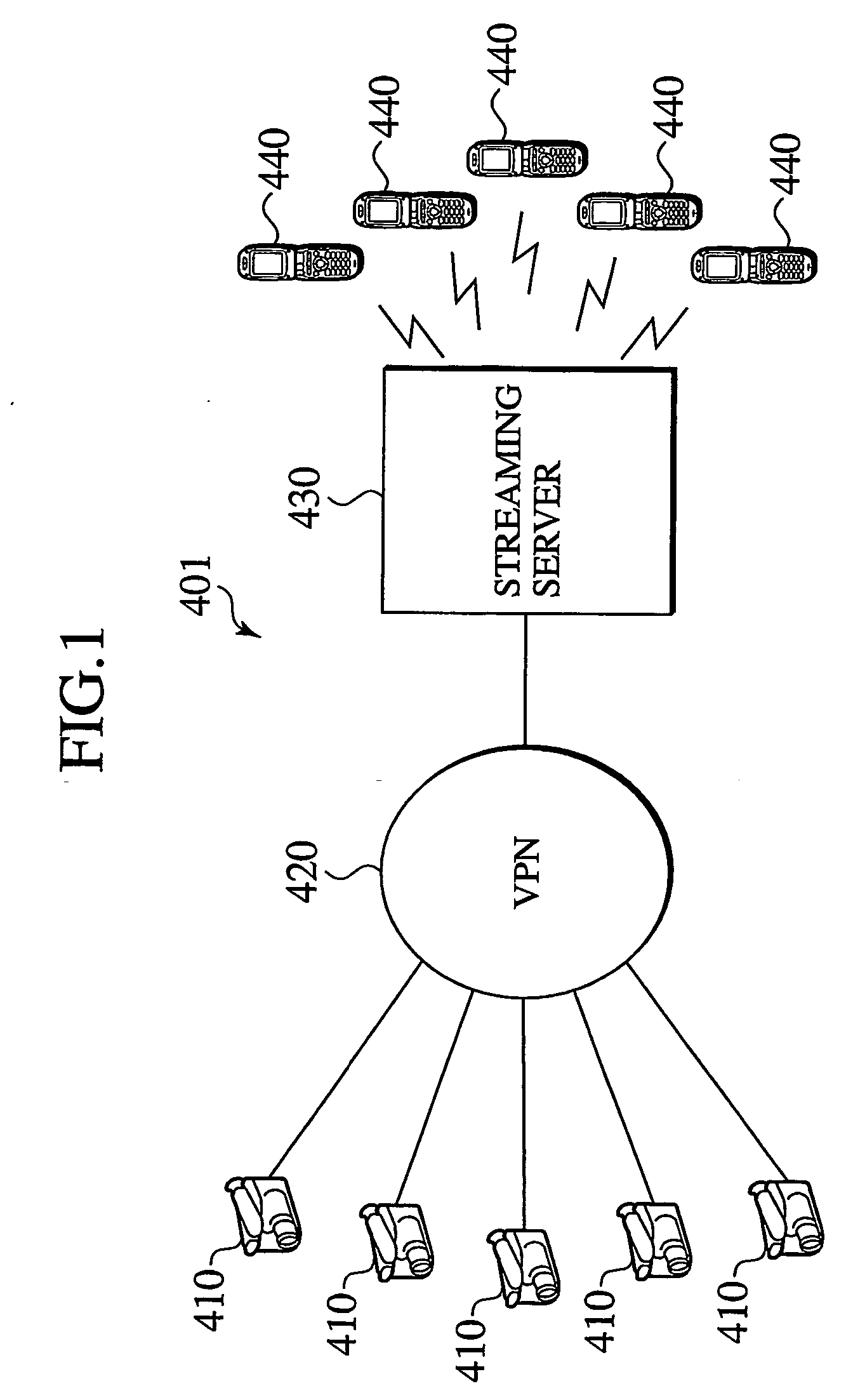
TECHNICAL FIELD [0001] The present invention relates to a communication system and a transfer device. BACKGROUND ART [0002] Conventionally, there have been communication systems, which transmit video data to mobile terminals by streaming (for example, “W-CDMA MOBILE COMMUNICATIONS SYSTEM” edited by Keiji Tachikawa, p. 357-360,Maruzen, Jun. 25, 2001). For example, a communication system, which transmits video data by streaming shown in FIG. 1 has been used. In a communication system 401 shown in FIG. 1, a plurality of cameras 410 recording video data, and a streaming server 430 transmitting video data to a plurality of mobile terminals 440 by streaming, connect to a single virtual private network (hereafter, referred to as VPN) 420, and are connected to each other via the VPN 420. In the communication system 401, a camera 410 transmits video data to the streaming server 430 via the VPN 420. The streaming server 430 then obtains and transmits the video data transmitted from the camera...

Claims


Application Information

Patent Timeline
IPC IPC(8): H04L9/32H04L12/46H04L12/70H04N7/18H04L29/06H04L29/08H04L29/12H04N7/173H04N21/2187H04N21/239H04N21/258H04N21/475
CPCH04L12/4604H04L65/80H04L29/06H04L29/06027H04L29/12009H04L29/1233H04L29/12584H04L29/12877H04L61/2596H04L61/604H04L63/0272H04L63/083H04N7/162H04N7/17318H04N21/2187H04N21/25875H04N21/41407H04N21/472H04W4/00H04L65/4076H04L65/4084H04L12/4641H04L61/00H04L61/25H04L2101/64H04L65/611H04L65/612H04L9/32H04L12/28H04L12/46H04L9/40H04L65/1101
Inventor KODAMA, MITSURUTSUJI, KENJIROUNISHIMURA, ISSEI
Owner NTT DOCOMO INC
Learn More