Method, device, and system for controlling dissolved amount of gas

Inactive Publication Date: 2006-07-06
TETABUHIKO FUJISATO +1
View PDF0 Cites 20 Cited by
  • Summary
  • Abstract
  • Description
  • Claims
  • Application Information

AI Technical Summary

Benefits of technology

[0055] (1) The gas suction force and the compression force of the compressor is used as the source of power of gas dissolution. Thus, operation is achieved merely by opening and closing the valves at respective places. This provides good operability and controllability. Further, the pressurized gas energy after the dissolving process is recycled efficiently. This enhances energy saving.
[0056] (2) In a lake bottom region having a low water temperature in a lake, a dammed lake, or the like, oxygen is dissolved at a high concentration into the static pressure water of the water area, so that the discharged water has almost the same water temperature. Thus, the oxygen dissolving water is prevented from rising from the place of discharge, and hence settled there. This avoids loss, and hence has high efficiency and good economy.
[0057] This sup

Problems solved by technology

Further, this remarkably reduces the resistance of the liquid injected into the container, so that a sm

Method used


Image

  • Method, device, and system for controlling dissolved amount of gas
  • Method, device, and system for controlling dissolved amount of gas
  • Method, device, and system for controlling dissolved amount of gas

Examples


Example

Embodiment 1

[0071] A device for controlling a dissolved amount of gas according to Embodiment 1 relevant to a method for controlling a dissolved amount of gas according to the first aspect of the invention and a device for controlling a dissolved amount of gas according to the second aspect is described below with reference to the drawings.

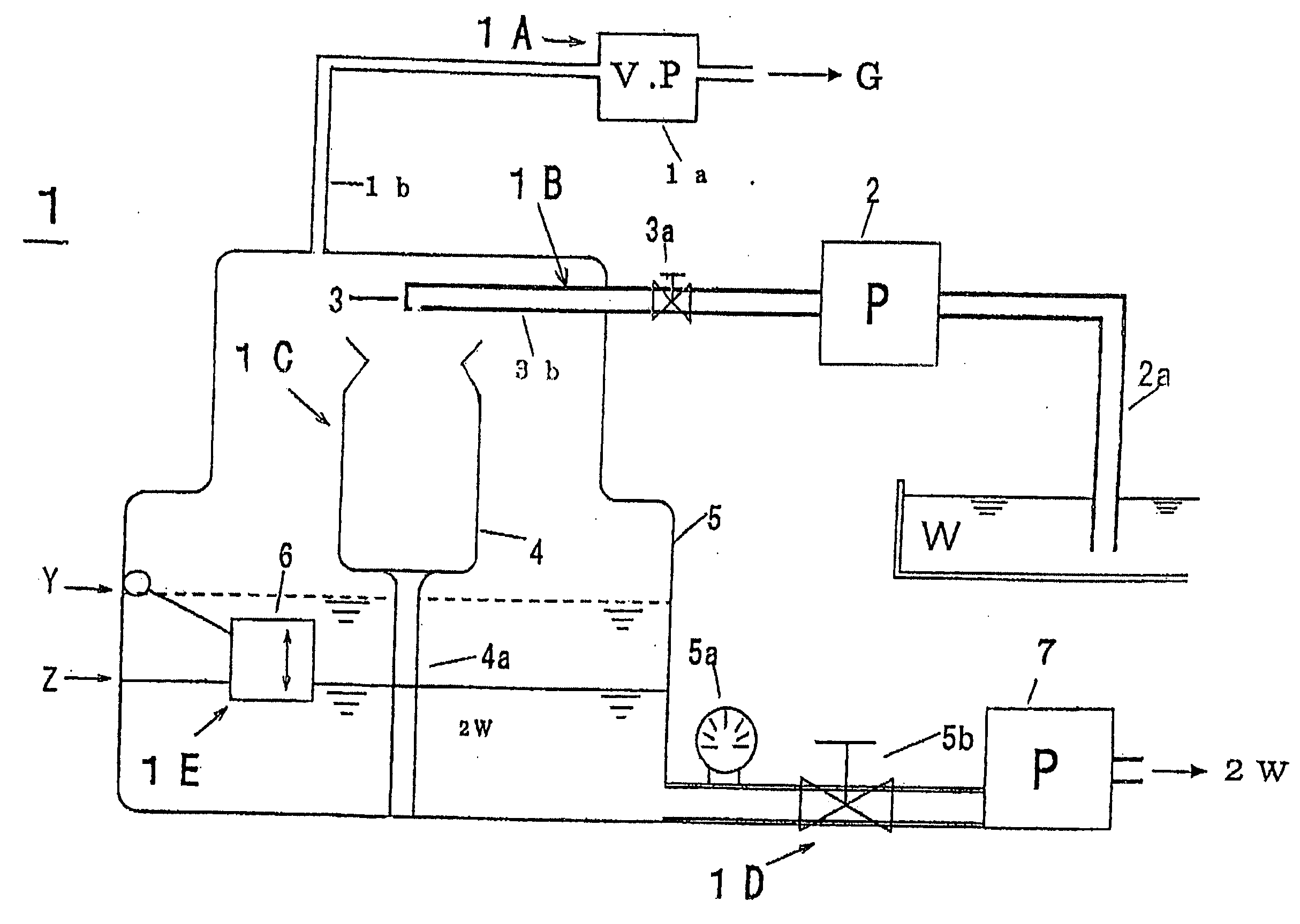
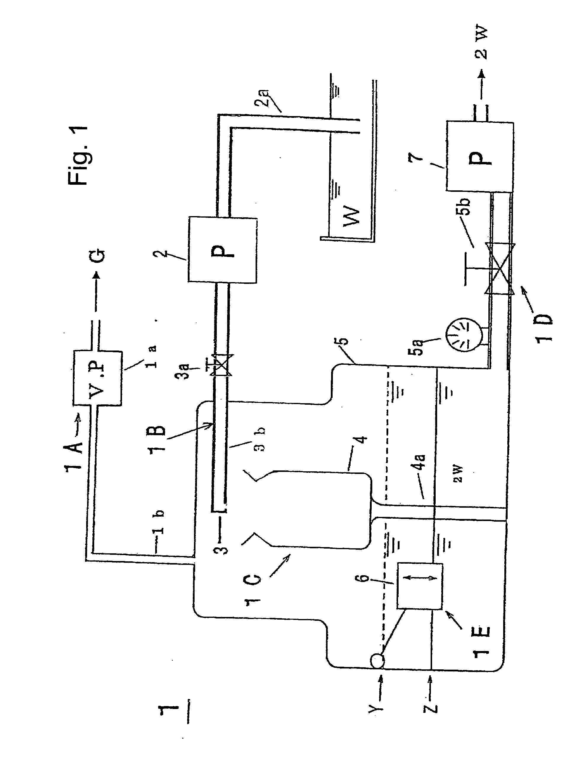
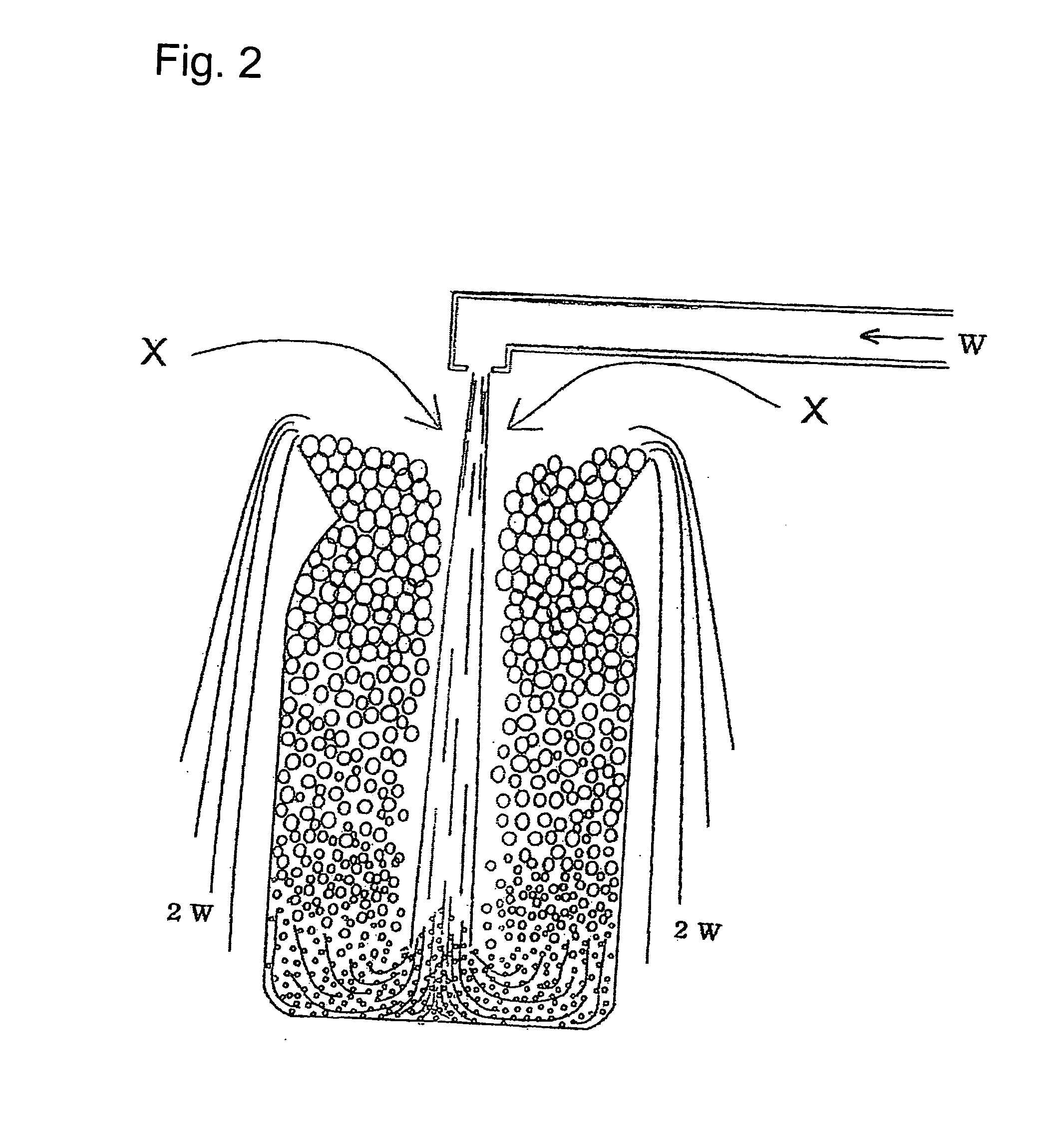
[0072]FIG. 1 is a front view of a device for controlling a dissolved amount of gas according to Embodiment 1 of the invention. FIG. 2 is a schematic diagram showing the situation that a treated fluid W injected from a nozzle involves in a large amount of surrounding gas X and thereby generates a large amount of air bubbles at a central bottom part of a liquid foam generating container, so that a large amount of air bubbles rise from a bottom peripheral wall of the container by an effect of buoyancy and aggregate and thereby grow rapidly, so that the air bubbles are separated upward from the liquid by an effect of gravity, then change into liquid...

Example

Embodiment 2

[0086] A device for controlling a dissolved amount of gas relevant to a method for controlling a dissolved amount of gas according to the first aspect of the invention and a device for controlling a dissolved amount of gas according to the third aspect is described below with reference to the drawings.

[0087]FIG. 4 is a front view of a device for controlling a dissolved amount of gas according to Embodiment 2 of the invention. In comparison with Japanese Published Unexamined Patent Application No. 2003-126884 “Water Treatment Device and Water Treatment Process” filed by the present applicant, the method is almost the same in the point that treated fluid is raised upward by approximately 10 m by using a vacuum pump or the like so that a reduced pressure space is generated over the treated fluid. However, a large difference is that the deaeration process is performed in the reduced pressure space onto a liquid film in the surface of the liquid bubbles where the gas dissol...

Example

Embodiment 3

[0101] A device for controlling a dissolved amount of gas according to Embodiment 3 relevant to a method for controlling a dissolved amount of gas according to the first aspect of the invention and a device for controlling a dissolved amount of gas according to the fourth and fifth aspect is described below with reference to the drawings.

[0102]FIG. 5 is a front view of a device for controlling a dissolved amount of gas according to Embodiment 3 of the invention.

[0103] In FIG. 5, numeral 20 indicates a device for controlling a dissolved amount of gas according to Embodiment 3. Numeral 21 indicates a pressure resisting tank capable of bearing the tap water pressure. Numeral 21a indicates a base for stabilizing the tank 21. Numeral 22 indicates a nozzle for involving in a large amount of gas of a gas space X in the tank when pressurized fluid is injected from a hot water supply machine or a tap water system. Numeral 22a indicates a supply valve capable of controlling the...


PUM

PropertyMeasurementUnit
Lengthaaaaaaaaaa
Lengthaaaaaaaaaa
Lengthaaaaaaaaaa

Abstract

A device for controlling a dissolved amount of gas. The device is formed of: a pressure reducing part which is constructed by connecting a hole provided at an upper part of a closed tank to a vacuum pump through a pipe; an injection supply part for injecting treated fluid pressurized by a pressurizing pump from the upper part of the tank; a liquid foam generating part provided with a container where the injected treated fluid is received, then gas of the reduced pressure space is involved in, and an air bubble group rises along an inner peripheral wall and is separated from the liquid, and then changes into liquid bubbles in an upper region; a recovery pump part for allowing the liquid bubbles having overflowed from an upper end of the container; and a tank water level sensor part for transmitting the information for maintaining a water level of the treated fluid.

Description

TECHNICAL FIELD [0001] The present invention relates to a method, a device, and a system for controlling a dissolved amount of gas which can be used in various fields: to dissolve oxygen into water efficiently so as to generate an environment appropriate for animals and plants; to mix high concentration gas dissolving liquid into treated fluid and then generate fine air bubbles by reduced pressure foaming so as to perform floatation separation of suspended solids (SS, hereinafter) by means of aggregation between the air bubbles and the SS in the treated fluid; fabrication of gas dissolution function water for washing in a semiconductor fabrication process, in which a specific gas component is dissolved; to perform deaeration removal of harmful volatile gas or the like dissolved in liquid (such as factory waste water, underground water, and fish and shellfish nursery water); and to fabricate deaerated water for boiler feed water and ultrasonic cleaning. On the contrary, since high co...

Claims


Application Information

Patent Timeline
IPC IPC(8): B01D53/14B01D19/00B01F3/04C02F1/20
CPCB01D19/0005B01D19/0042B01D19/0063B01F3/0446C02F1/20C02F2209/42C02F2301/063C02F2303/12Y10S261/26B01F23/232B01D19/00B01F21/00B01F23/2326B01F35/2217
Inventor FUKAGAWA, MASAYUKIHADANO, KESAYOSHIFUJISATO, TETSUHIKOFUJISATO, RYOSAKU
Owner TETABUHIKO FUJISATO
Why Eureka
Try Eureka