
Oil drain passage structure of cylinder block and core structure thereof

a technology of oil drain passage and cylinder block, which is applied in the direction of machines/engines, foundry patterns, moulding apparatus, etc., can solve the problems of undercutting the performance of the engine, unsatisfactory shifting of the passage core, etc., and achieves the effect of reducing engine noise, vibration, and harshness

Active Publication Date: 2006-07-06
HYUNDAI MOTOR CO LTD
View PDF8 Cites 10 Cited by
  • Summary
  • Abstract
  • Description
  • Claims
  • Application Information

AI Technical Summary

Benefits of technology

[0005] The present invention provides methods and apparatuses to achieve precise manufacturing of drain passages such as those used for oil return and blow-by gas discharge in a cylinder block. Additionally, the present invention provides methods and apparatuses that improve the molding of the cylinder block, thereby forming a stable and rigid cylinder block structure which can reduce engine noise, vibration, and harshness (NVH).

Problems solved by technology

However, a problem frequently encountered in the art involves the undesirable shifting of these passage cores upon the addition of molten metal during the casting process.
As a result, the cylinder block produced has drain passages that deviate from the original design and undercuts the performance of the engine, e.g. Noise, Vibration, and Harshness (NVH) levels, and structural rigidity of the cylinder block.

Method used


Image

  • Oil drain passage structure of cylinder block and core structure thereof
  • Oil drain passage structure of cylinder block and core structure thereof
  • Oil drain passage structure of cylinder block and core structure thereof

Examples


Embodiment Construction

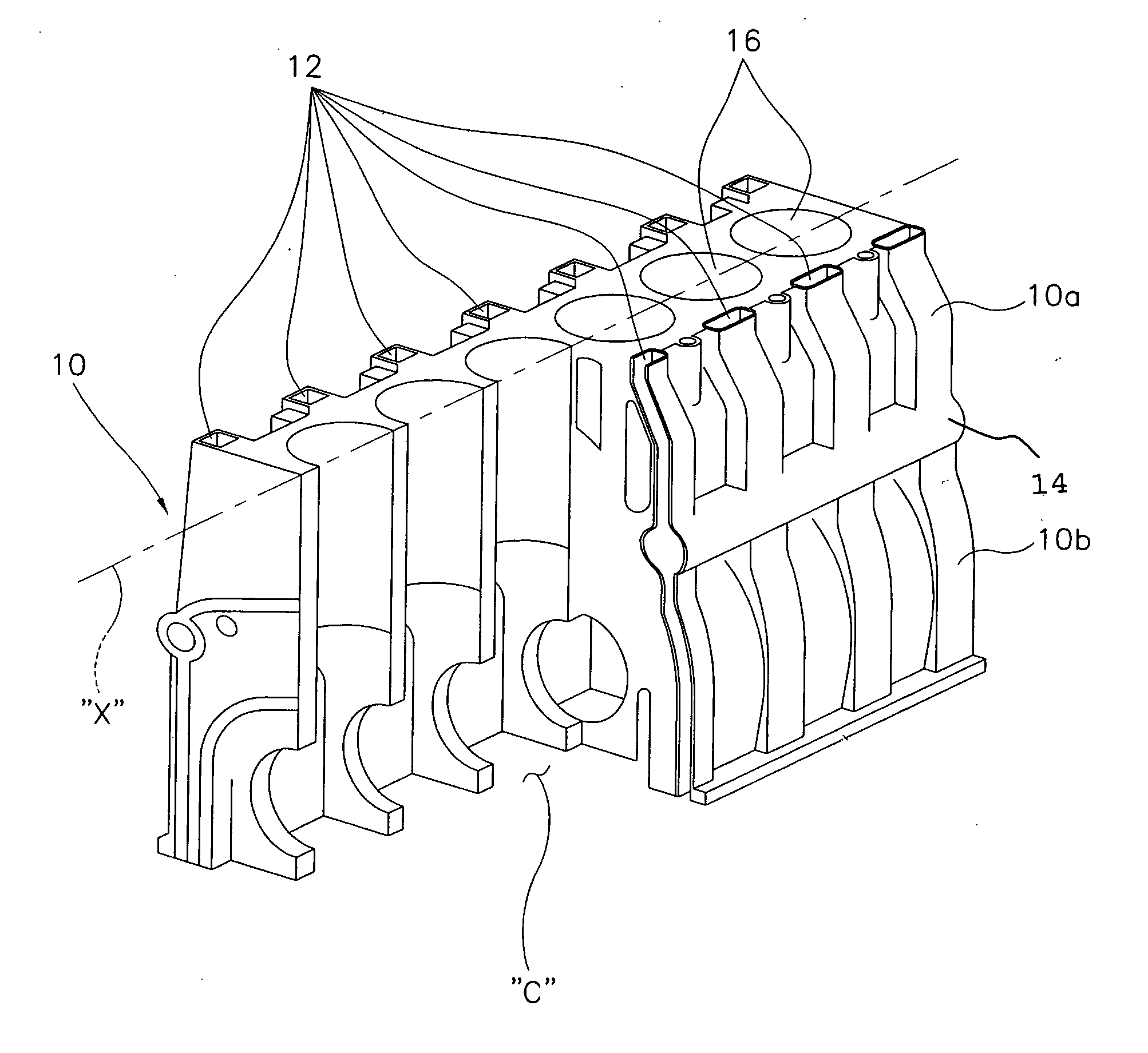
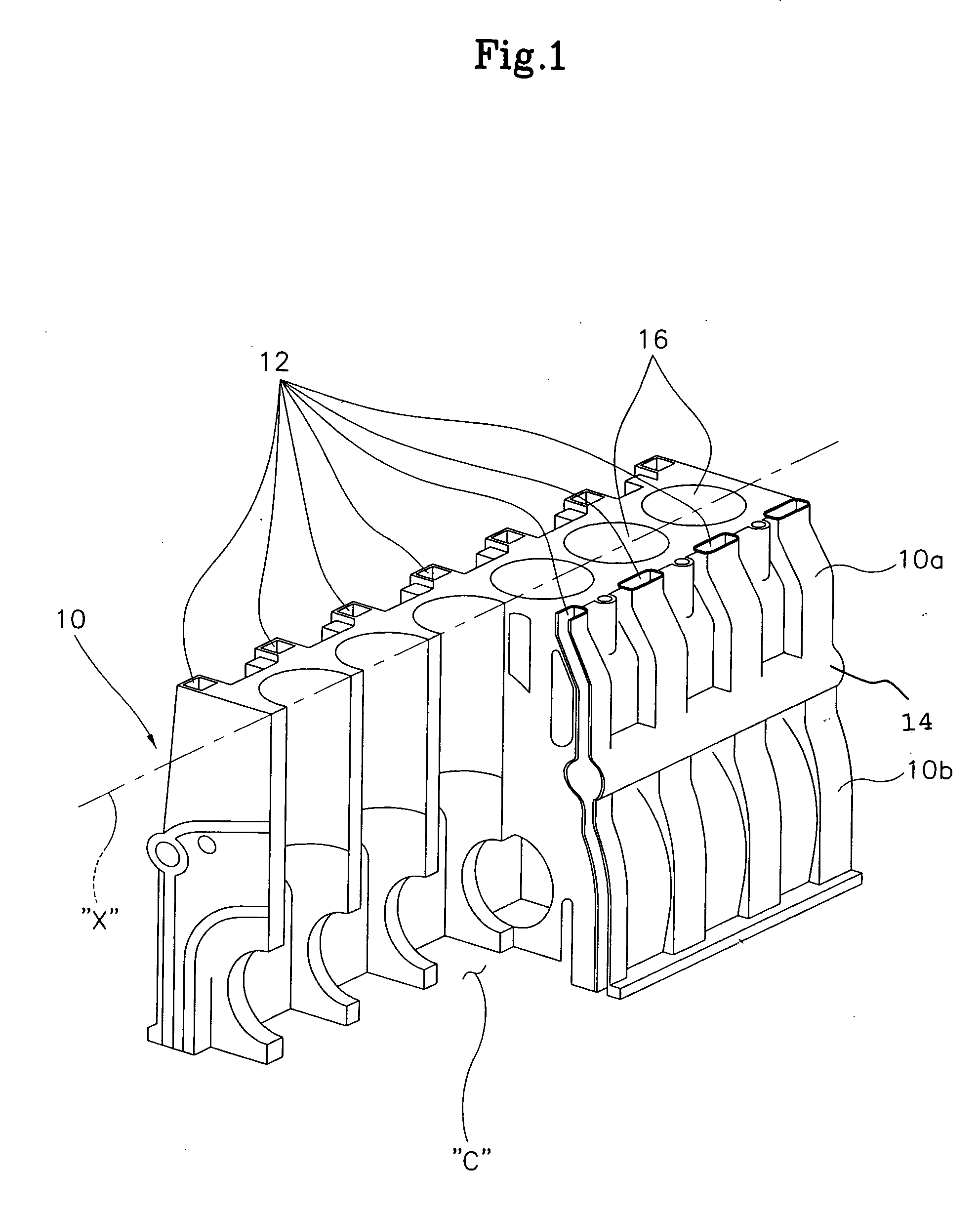
[0009] In one embodiment of the present invention as shown in FIG. 1, a plurality of drain passages, which can be used as oil drain and blow-by gas drain passages, in a cylinder block 10 are symmetrically positioned relative to a central axis (X) of cylinder block 10. The plurality of vertical cores are interconnected to form an integral truss that precisely forms an engine cylinder block which is substantially true to the original design so as to achieve the intended weight / rigidity ratio.

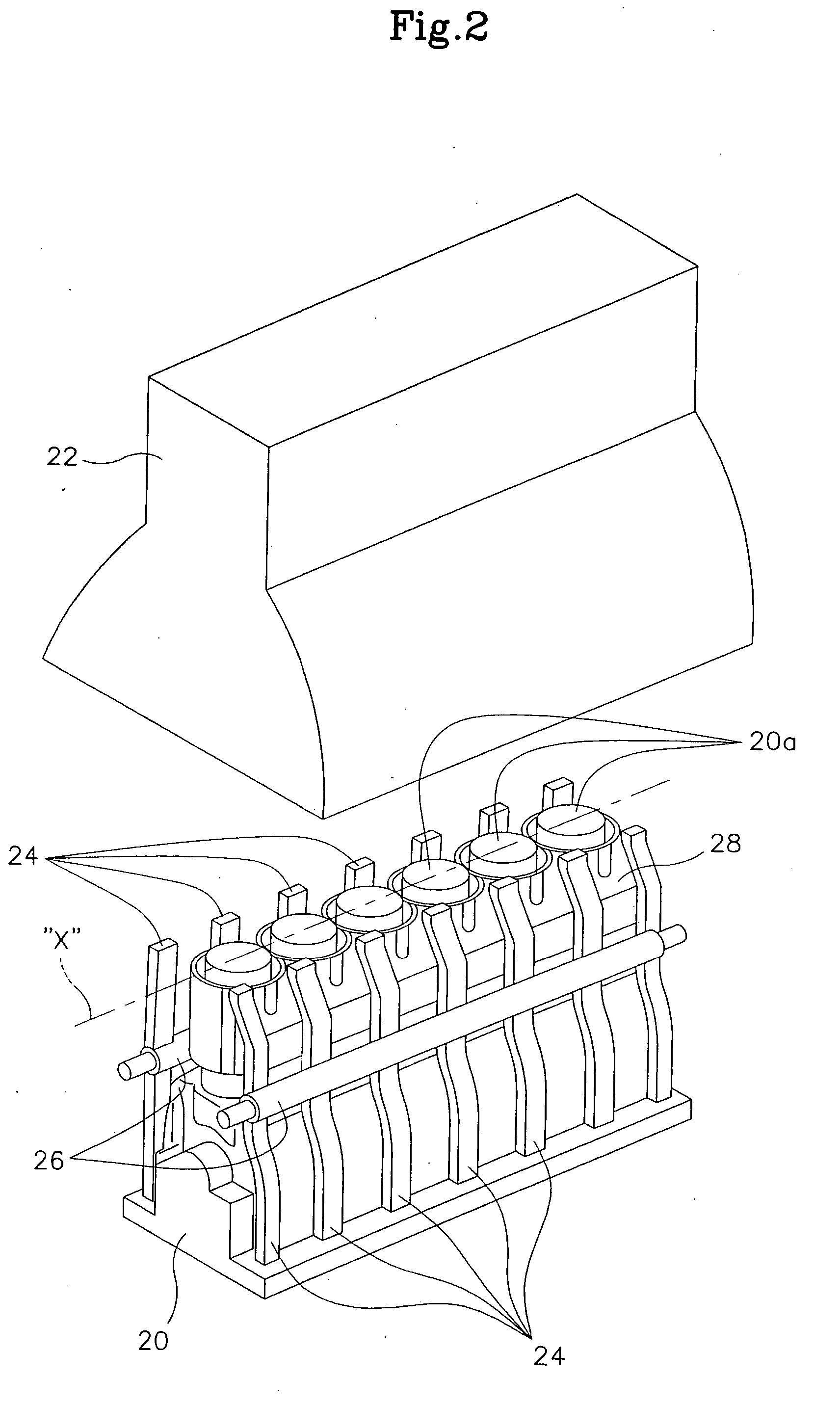
[0010] As shown in FIG. 1 and FIG. 2 and used herein, the central axis (X) of the cylinder block is a line that runs through the centers of cylinder bores 16. The structure of the oil drain passages, illustrated in FIG. 1, is characterized by a plurality of vertical passages 12 interconnected by a connecting passage 14

[0011] In some embodiments of the present invention, vertical passages 12 are arranged longitudinally in cylinder block 10 and interconnected by a connecting passage 14 which runs l...


PUM

PropertyMeasurementUnit
Structureaaaaaaaaaa

Abstract

The present invention provides an apparatus for achieving precise manufacturing of drain passages such as those used for oil return and blow-by gas discharge in a cylinder block. Grid-like oil drain passage and corresponding core structures are disclosed herein; the oil drain passage structure comprises a plurality of vertical passages that are arranged longitudinally with respect to the cylinder block, wherein the vertical passages are interconnected by a connecting passage that runs longitudinally through the central portions of the vertical passages.

Description

CROSS-REFERENCE TO RELATED APPLICATIONS [0001] This application is based on and claims priority of Korean Patent Application No. 10-2004-0109588, filed on Dec. 21, 2004, with the Korean Intellectual Property Office, the disclosure of which is fully incorporated herein by reference. FIELD OF THE INVENTION [0002] The present invention relates to cylinder blocks for use in engines. More particularly, the present invention relates to processes and apparatuses for forming drain passages in engine cylinder blocks. BACKGROUND OF THE INVENTION [0003] Cylinder block structures are well known in the art. Generally, a cylinder block contains numerous internal passages that are oriented in directions directions. Among these internal passages are oil drain passages that individually extend from an upper valley of the cylinder block to the oil pan. It follows that a mold used to cast the cylinder block should comprise a plurality of cores which form these oil drain passages. [0004] However, a pro...

Claims


Application Information

Patent Timeline
IPC IPC(8): F02F1/10B22D45/00
CPCB22C9/103B22C9/22F01M11/02F02F7/0007F01M1/06
Inventor KIM, JONG-WON
Owner HYUNDAI MOTOR CO LTD
Learn More