Condensation reduction and management systems in a gas flow delivery system

a management system and gas flow technology, applied in the direction of breathing filters, other medical devices, breathing protection, etc., can solve the problems of unpleasant gurgling sound of gas flowing through accumulated condensation, undesirable condensation in patient circuit and/or patient interface, and increased risk of bacteria formation in moist areas, etc., to reduce heat loss from the conduit, reduce condensation, isolate, control or reduce condensation in patient circuit and patient interfa

Inactive Publication Date: 2006-07-06
RIC INVESTMENTS LLC
View PDF52 Cites 79 Cited by
  • Summary
  • Abstract
  • Description
  • Claims
  • Application Information

AI Technical Summary

Benefits of technology

[0011] Accordingly, it is an object of the present invention to provide techniques for isolating, controlling, or reducing condensation in a patient circuit and patient interface. This object is achieved according to one embodiment of the present invention by providing a patient circuit that includes a conduit having a first end portion, a second end portion, and a lumen defined therein from the first end portion to the second end portion. A radiant barrier is associated with the conduit such that the radiant barrier is disposed between an ambient environment and the lumen. The radiant barrier is a low emissivity material that reduces heat loss from the conduit due to radiant energy. By reducing radiation heat loss from the conduit, the gas flow in the conduit is not cooled as much as in current systems, which use only an insulation layer to prevent heat loss due to conduction. By reducing the amount of cooling, condensation is reduced.

Problems solved by technology

Condensation in the patient circuit and / or patient interface is undesirable for several reasons.
Moist areas are also more prone to formation of bacteria.
Additionally, gas flowing through any accumulated condensation may generate an annoying gurgling sound.
This process is disruptive and may interfere with the patient's therapy.

Method used


Image

  • Condensation reduction and management systems in a gas flow delivery system
  • Condensation reduction and management systems in a gas flow delivery system
  • Condensation reduction and management systems in a gas flow delivery system

Examples


Embodiment Construction

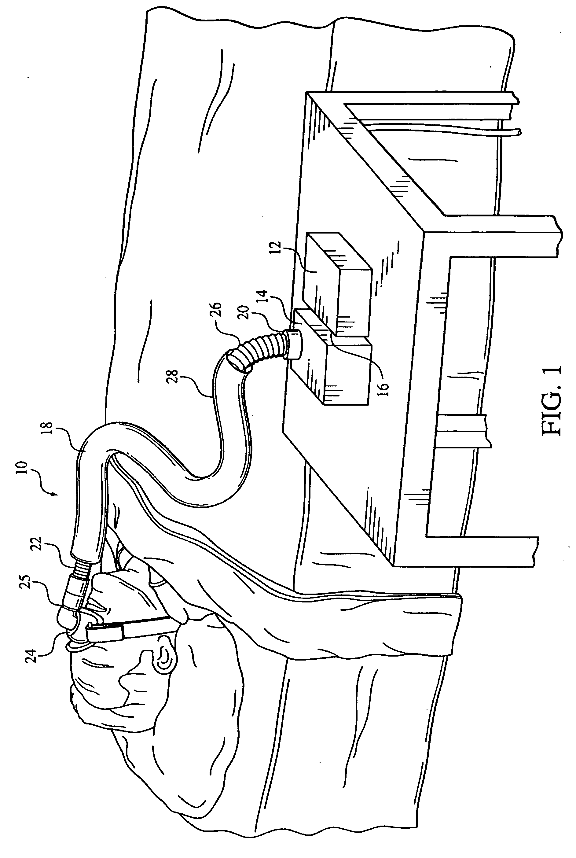
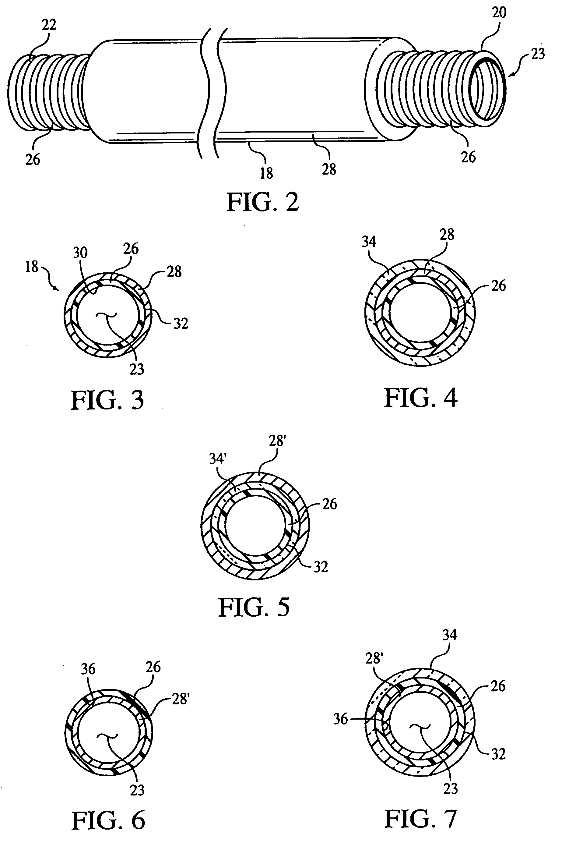
[0035] Referring first to FIGS. 1-3, a gas flow delivery system 10 for delivering a flow of gas to an airway of a patient is illustrated. Gas flow delivery system 10 comprises a pressure generating device 12 that produces a flow of gas and an optional humidifier 14 coupled to an outlet 16 of the pressure generating device 12. A gas delivery conduit, which is also referred to as a patient circuit, 18 is coupled to the outlet of the humidifier. Of course, if the humidifier is omitted, the patient circuit would be coupled to the outlet of the gas flow generating device.

[0036] Pressure generating device 12 is any conventional ventilation or pressure support system. Examples of such systems include, but are not limited to: a ventilator, continuous positive airway pressure (CPAP) device, or a variable pressure device, e.g. an auto-titrating device, proportional assist ventilation (PAV®) device, proportional positive airway pressure (PPAP®) device, C-Flex™ device, Bi-Flex™ device, or a Bi...


PUM


Abstract

Condensation management techniques for a gas flow delivery system. The techniques include providing a radiant barrier associated with patient circuit and/or a patient interface, providing a water trap and/or an absorbent insert in the patient interface device, or a combination of these techniques. The radiant barrier prevents condensation from forming in the patient circuit and/or the patient interface. The water trap and absorbent insert in the patient interface control condensation that reaches or forms in the interior of the patient interface to prevent it from interfering the user of the gas delivery system.

Description

CROSS-REFERENCE TO RELATED APPLICATIONS [0001] This application claims priority under 35 U.S.C. § 119(e) from provisional U.S. patent application No. 60 / 637,339, filed Dec. 17, 2004, the contents of which are incorporated herein by reference.BACKGROUND OF THE INVENTION [0002] 1. Field of the Invention [0003] The present invention relates to a system for isolating, controlling, or reducing condensation in a patient circuit or in a patient interface in a gas flow delivery system. [0004] 2. Description of the Related Art [0005] Gas flow delivery systems are used to deliver a flow of gas to an airway of a subject. Such systems are typically used in the medical field to deliver gas to a patient. Examples of gas flow delivery systems in the medical field include a ventilator or respirator, which replaces or supplements a patient's respiration, and a pressure support system, which provides a flow of gas to an airway of a patient at an elevated pressure to treat a medical disorder, such as ...

Claims


Application Information

Patent Timeline
Patent Type & Authority Applications(United States)
IPC IPC(8): A62B7/10A61M16/00
CPCA61M16/06A61M16/0808A61M16/0875A61M16/0622A61M16/0057A61M16/0616A61M16/0633A61M16/0638A61M16/0655A61M2205/0238
Inventor DAVIDOWSKI, DOUG L.HO, PETER CHI FAIBUSCH, LANCELORDO, RICHARD J.MATULA, JEROME JR.
Owner RIC INVESTMENTS LLC
Why Eureka
Try Eureka