Swept-wing box-type aircraft with high fligh static stability

Inactive Publication Date: 2006-07-06
FREDIANI ALDO
View PDF9 Cites 40 Cited by
  • Summary
  • Abstract
  • Description
  • Claims
  • Application Information

AI Technical Summary

Benefits of technology

[0008] The object of the present invention is, therefore, to provide a box type aircraft with opposedly swept wings of the type described in the

Problems solved by technology

As a matter of fact, it was already proposed in the past to connect the rear wing to the top fin, instead of the fuselage, both for box wing (see U.S. Pat. No. 3,834,654) and for diamond shaped wings (see U.S. Pat. No. 4,365,773), but these solutions were dropped due to flutter problems.
In fact, the efficiency of the rear wing at the connection to the fuselage is aerodynamically low due to the shape of the wing an

Method used


Image

  • Swept-wing box-type aircraft with high fligh static stability
  • Swept-wing box-type aircraft with high fligh static stability
  • Swept-wing box-type aircraft with high fligh static stability

Examples


Embodiment Construction

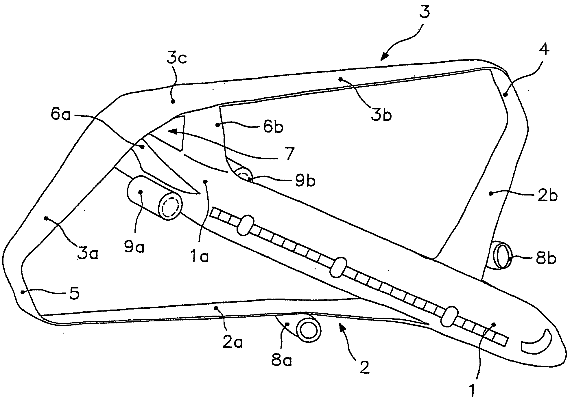
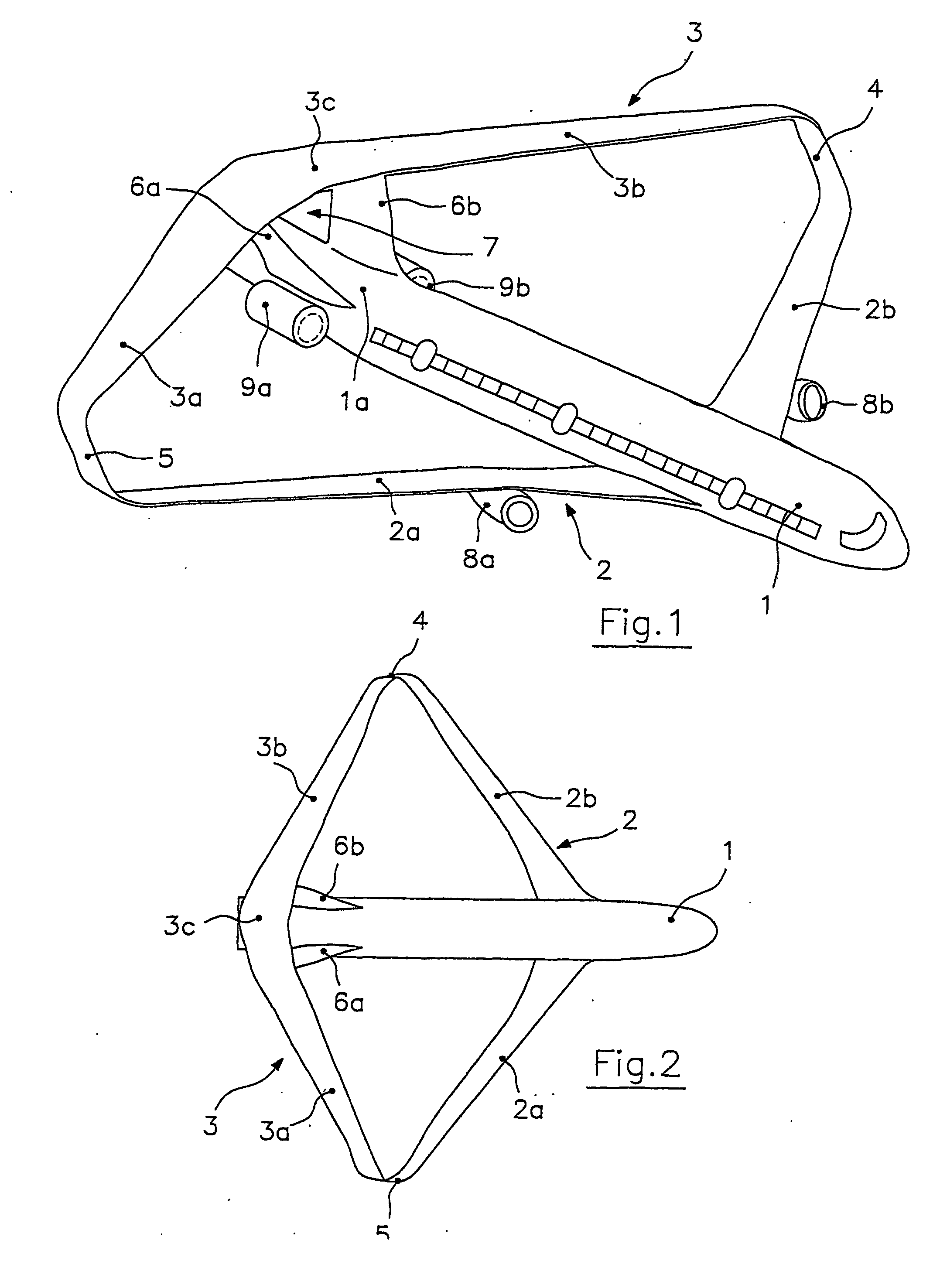
[0019] With reference to FIGS. 1 to 4, the aircraft according to the present invention comprises a fuselage 1, a front wing 2 formed by half wings 2a and 2b and a rear wing 3 formed by half wings 3a and 3b, said half-wings 2a, b and 3a, b extending from opposite sides of fuselage 1. The front wing 2 and rear wing 3 have opposite sweep angles; in particular, the sweep angle is positive for front wing 2 and negative for rear wing 3. Besides, the front wing extends from the bottom fuselage 1 and crosses the fuselage under the cargo deck in such a way that the cargo capacity is significantly improved, while rear wing 3 extends over fuselage 1. As a pure example, the sweep angle of half wings 2a and 2b with respect to the longitudinal axis of fuselage 1 is comprised between 30° and 45°, while the angle of half wings 3a and 3b may vary from −18 to −25°.

[0020] The average lying planes of front wing 2 and rear wing 3 are close to horizontal and spaced apart from each other and their ends a...


PUM


Abstract

Swept-wing box-type aircraft comprising a fuselage and a lifting system formed by two substantially horizontal wings. One of the wings has a positive sweep angle, while the other has a negative sweep angle, the wings lying in planes spaced apart from one another and joined by two vertical wings extending from their ends. The positively swept wing is the front wing and extends from the bottom of the fuselage, whereas the negatively swept wing is the rear wing and extends generally continuously above the fuselage, the fuselage being provided with a pair of fins at its tail section. The fins are joined at their ends to the rear wing, the fins, the rear wing and the fuselage defining an aerodynamic channel along which the surface of the fuselage is substantially flat.

Description

FIELD OF THE INVENTION [0001] The present invention relates to a box-plane aircraft with high static stability of flight. More particularly the invention relates to the configuration of such an aircraft. BACKGROUND ART [0002] European Patent No. 716978, in the name of the same Applicant, discloses a large dimension aircraft with a lifting system having two horizontal wings, the front one with a positive sweep angle and rear one with a negative sweep angle. The two wings are positioned on two substantially parallel planes and two vertical wings connect the tips of the horizontal wings. The lifting system, as a whole, is therefore of the so-called “box” type in the front view. In the case that the two horizontal wings have the same lift and the lift distribution on the vertical wings is butterfly shaped, the lifting system has the minimum induced drag among all the lifting systems included within the geometrical space delimited by the wings. Considering that, in this type of aircraft,...

Claims


Application Information

Patent Timeline
IPC IPC(8): B64C39/12B64C39/06
CPCB64C39/068
Inventor FREDIANI, ALDO
Owner FREDIANI ALDO
Why Eureka
Try Eureka