Electromagnetic actuator

a technology of electromagnetic actuators and actuators, which is applied in the direction of magnetic bodies, magnetic circuit shapes/forms/construction, instruments, etc., can solve the problems of complex assembly operation, inability to wind the coils around the stator having such a shape directly, and inability to manufacture the above-described electromagnetic actuators 100/b>, so as to achieve efficient winding of the coils around the stator, wide angle range, and efficient manufacturing

Active Publication Date: 2006-07-06
SEIKO INSTR INC
View PDF6 Cites 7 Cited by
  • Summary
  • Abstract
  • Description
  • Claims
  • Application Information

AI Technical Summary

Benefits of technology

[0011] In accordance with the present invention, when the coil is wound around the stator with the use of a coil-winding apparatus in the manufacturing process, the ends of the stator, which can be obstacles, are arranged within a range from 15 to 90 degrees. It is therefore possible to wind the coil around the stator efficiently without a problem. It is also possible to set the ends of the stator to have a wider angle range, thereby enabling to retain the original capabilities of the electromagnetic actuator with the ends set to magnetic poles. Hence, in accordance with the present invention, it is possible to provide the electromagnetic actuator that can be manufactured efficiently, whereas the originally provided capabilities of the electromagnetic actuator are retained.
[0012] The afore-described angle range is set to a maximum range in which the ends of the stator are made to be obstacles, while the coil wire is being wound around the stator by use of the coil-winding apparatus. In addition, preferably, the stator includes shoulder portions that suppress misalignment or disintegration of the coils. With such a stator, the coil can be positioned on a given position when the coil is wound around the stator, and the wound coil can be retained stably on the given position.
[0013] As described above, in accordance with the present invention, it is possible to provide an electromagnetic actuator in which the fabrication efficiency can be promoted and originally provided capabilities of the electromagnetic actuator can be retained.

Problems solved by technology

There is a drawback, however, in the production of the above-described electromagnetic actuator 100.
In the practical manufacturing process, it is impossible to wind the coils around the stator having such a shape directly.
In the manufacturing process of the above-described electromagnetic actuator 100, more parts are needed than those of the conventional actuators, resulting in the complicated assembling operation and increased man-hour.

Method used


Image

  • Electromagnetic actuator
  • Electromagnetic actuator
  • Electromagnetic actuator

Examples


Embodiment Construction

[0019] A description will now be given, with reference to the accompanying drawings, a shutter apparatus in accordance with an embodiment of the present invention.

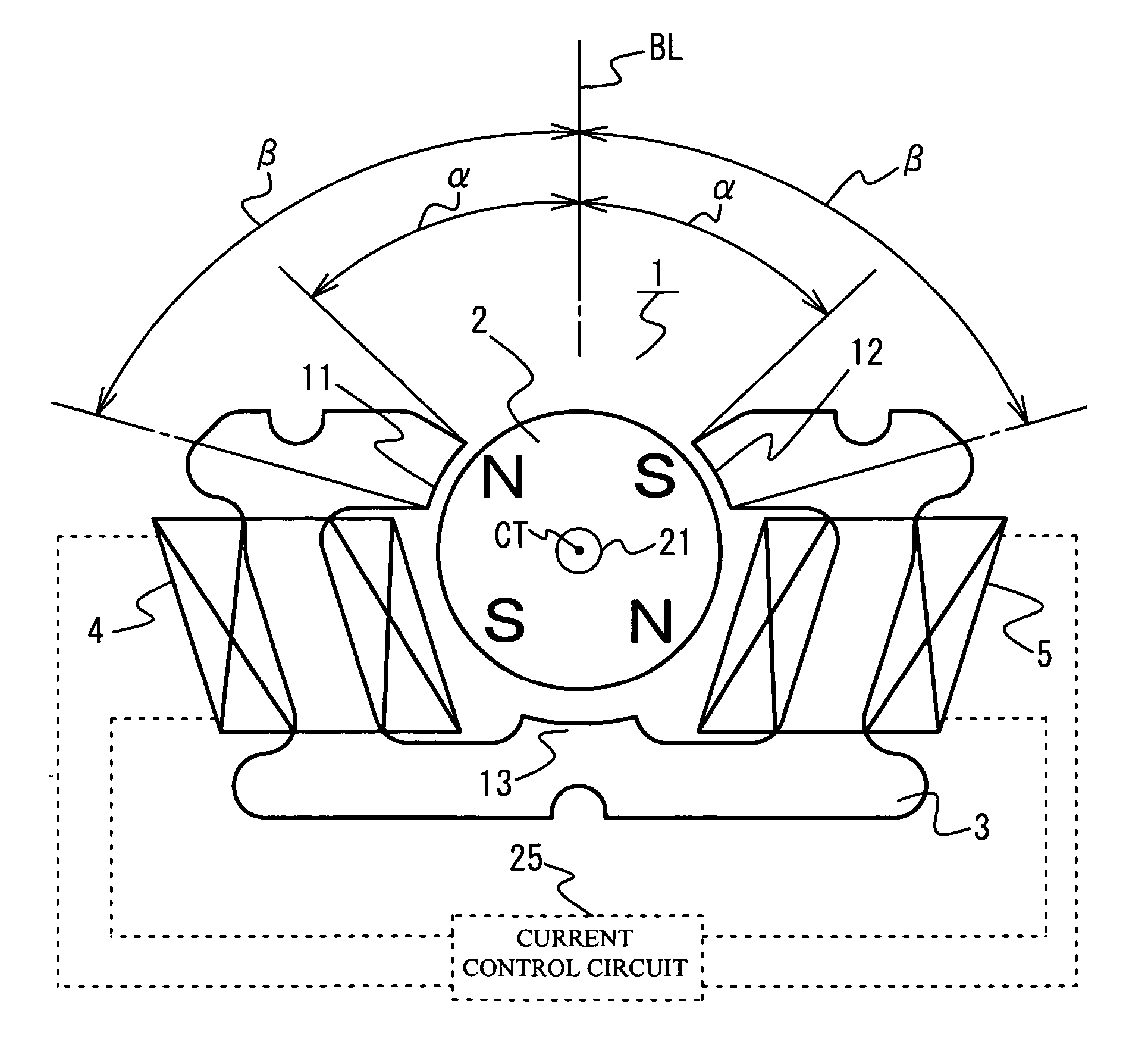
[0020]FIG. 1 is a view showing main components of an electromagnetic actuator 1 in accordance with an embodiment of the present invention. The electromagnetic actuator 1 includes a rotor 2 and a stator 3. The rotor 2 is arranged rotatably in both directions in the center of the electromagnetic actuator 1. The stator 3 is arranged to face the outer surface of the rotor 2. The rotor 2 has a cylindrical shape, and has a circular shape at cross section. The stator 3 has a C-shaped planar shape, and is integrally formed. The stator 3 is formed substantially symmetrically with respect to a base line BL of geometric centerline (which runs across the center of the rotor 2, and is referred to as virtual base line). A rotation axis 21 of the rotor 2 is provided in a space surrounded by the C-shaped stator 3, and the rotor 2 is hous...


PUM

PropertyMeasurementUnit
angleaaaaaaaaaa
angleaaaaaaaaaa
angleaaaaaaaaaa

Abstract

An electromagnetic actuator has a rotor and a stator around which coils are wound to face portions of an outer surface of the rotor. The stator is C-shaped, the rotor is arranged so that a rotation axis thereof is existent in a space surrounded by the stator, and both ends of the stator are respectively formed within a range from 15 to 90 degrees from a virtual base line with respect to the rotation axis serving as a center, when the virtual base line is set to run a center of the rotation axis and separate the stator into left and right.

Description

BACKGROUND OF THE INVENTION [0001] 1. Field of the Invention [0002] This invention generally relates to small-sized electromagnetic actuators for use in optical apparatuses such as cameras, and more particularly, to an electromagnetic actuator having a stator of the shape in which coils can be wound around efficiently in the manufacturing process and the capabilities of the electromagnetic actuator can be maintained. [0003] 2. Description of the Related Art [0004] A shutter apparatus housed in an auto focus camera, for example, is driven by an electromagnetic actuator. In recent years, the sizes and weights of cameras have been decreased at a remarkable speed. This brings the need to provide small-sized and highly accurate electromagnetic actuators. Japanese Patent Application Publication No. 2-2382 (hereinafter, referred to as Document 1) discloses the electromagnetic actuator having two coils, which are provided around the stating element (stator) and are magnetically excited simu...

Claims


Application Information

Patent Timeline
Patent Type & Authority Applications(United States)
IPC IPC(8): H01F7/08H02K1/14H02K37/14
CPCH02K1/14H02K37/14H02K21/22
Inventor KAWAMOTO, HISASHITADA, SATORUNAKANO, TAKASHI
Owner SEIKO INSTR INC
Why Eureka
Try Eureka