Plasma display apparatus and driving method thereof

a technology of plasma display and driving method, which is applied in the direction of instruments, static indicating devices, etc., can solve the problems of increasing the duration of the display period, increasing the circuit cost, and affecting the operation of the display apparatus, so as to reduce the length of the subfield and prevent the effect of erroneous discharg

Inactive Publication Date: 2006-07-06
LG ELECTRONICS INC
View PDF20 Cites 7 Cited by
  • Summary
  • Abstract
  • Description
  • Claims
  • Application Information

AI Technical Summary

Benefits of technology

[0037] An object of the present invention is to provide a plasma display apparatus for preventing erroneous discharge, and reducing a length of a subfield to be adapted to a single scan method.

Problems solved by technology

However, the conventional plasma display apparatus has a drawback in that, in a PDP where the subfields are increased in number so as to reduce a factor of deteriorating the quality of picture such as a contour noise, a high-resolution PDP accompanying increase of the number of lines, or a high Xe-content PDP having a great discharge delay, the address period is increased and accordingly, the sustain period being a display period is relatively insufficient.
The double scan method has a drawback in that, due to addition of the driving integrated circuit, a circuit cost increases and a noise appears on a divided line.
However, the dual scan method has a drawback of causing reduction of a resolution.
Therefore, in the conventional plasma display apparatus, even by a discharge mechanism of the address discharge, the address period gets long.
Further, in the conventional plasma display apparatus, there is a drawback in that, during the erasure period (EP) of the (n−1)th subfield (SFn−1) and the reset period (RP) of the nth subfield (SFn), the discharge is generated at several times to initialize the discharge cells 1 and control the wall charges, thereby reducing the darkroom contrast and reducing a contrast ratio.
If the dark discharge is not normally generated in the setup period (SU), the discharge cells are not ideally initialized.
Further, if the dark discharge is not generated in the setup period (SU), the discharge cell is not in the optimal address condition soon after the reset period, thereby causing an abnormal discharge or an erroneous discharge.
Furthermore, in case where the positive wall charges are excessively accumulated on the scan electrode (Y) soon after the erasure period (EP) of the (n−1)th subfield (SFn−1), in the setup period (SU) of the nth subfield (SFn), when the positive sustain voltage (Vs) being an initiation voltage of the positive ramp waveform (PR) is applied to the scan electrode (Y), the discharge is strongly generated, thereby not uniformly initializing the whole cells.
In other words, when the erasure discharge is strongly generated in the erasure period prior to the reset period, the erroneous discharge can be caused.
As a result, in case where the erasure discharge is not generated or is very weakly generated in the erasure period prior to the reset period, the initialization is not normally performed, thereby causing the erroneous discharge or the abnormal discharge.
Resultantly, if the initial gap voltage (Vgini) does not satisfy the condition of the Equation 4 before the setup period (SU), the conventional plasma display apparatus can cause the erroneous discharge, the misdischarge, or the abnormal discharge, and decreases the operation margin.
In other words, in the conventional plasma display apparatus, in order to secure the operation reliability and the operation margin, an erasure operation in the erasure period (EP) should be normally performed but, as aforementioned, can be abnormally performed depending on the uniformity of the discharge cell or the use temperature of the PDP.
Further, in the conventional plasma display apparatus, the wall charges accumulated on the scan electrode (Y) and the sustain electrode (Z) before the reset period are not sufficient and therefore, the setup discharge occurs near the reset voltage (Vr) higher (100 V or more) than the sustain voltage (Vs).
Due to this, the conventional plasma display apparatus has a drawback in that an external applied voltage is increased for the setup discharge and as a result, high voltage devices should be included in a voltage source generating a high voltage and a scan drive circuit, thereby increasing a cost of the scan drive circuit.

Method used


Image

  • Plasma display apparatus and driving method thereof
  • Plasma display apparatus and driving method thereof
  • Plasma display apparatus and driving method thereof

Examples


Embodiment Construction

[0061] Preferred embodiments of the present invention will be described in a more detailed manner with reference to the drawings.

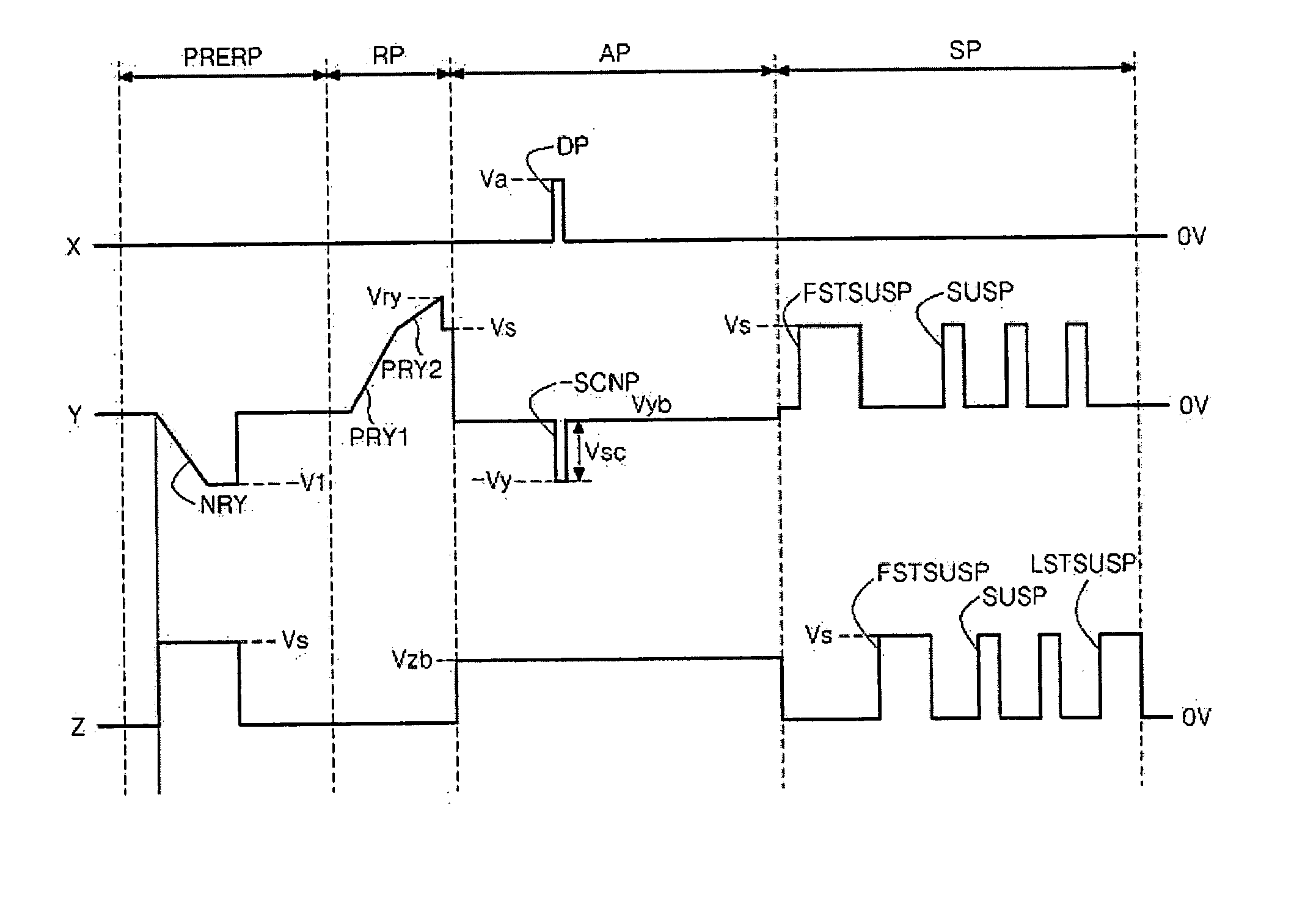
[0062] A plasma display apparatus according to the first embodiment of the present invention includes an electrode pair including a first electrode and a second electrode, a third electrode intersecting with the electrode pair, and a first electrode driver, a second electrode driver, and a third electrode driver for applying a driving signal to the respective electrodes. The first electrode driver applies a waveform that ramps-up to a reset voltage during a reset period and falls down to a base voltage substantially without ramp down.

[0063] The first electrode is a scan electrode, the second electrode is a sustain electrode, and the third electrode is an address electrode.

[0064]FIG. 6 illustrates a driving waveform applied to each electrode during one subfield period in a plasma display apparatus according to the first embodiment of the present inventio...


PUM


Abstract

A plasma display apparatus and a driving method thereof are provided. The apparatus includes: an electrode pair having a first electrode and a second electrode, and a third electrode intersecting with the electrode pair; and a first electrode driver, a second electrode driver, and a third electrode driver for applying a driving signal to the respective electrodes, wherein the first electrode driver applies a waveform ramping-up up to a reset voltage during a reset period and falling down to a base voltage substantially without a ramp down.

Description

BACKGROUND OF THE INVENTION [0001] 1. Field of the Invention [0002] The present invention relates to a plasma display apparatus, and more particularly, to a plasma display apparatus for improving a construction of a driving signal to be adapted to a single scan method and a driving method thereof. Further, the present invention relates to a plasma display apparatus and a driving method thereof, for preventing erroneous discharge and abnormal discharge, enhancing a darkroom contrast, and securing an operation margin. [0003] 2. Description of the Background Art [0004] Plasma display apparatus displays an image by exciting and emitting a phosphor using ultraviolet rays generated when an inert mixture gas is discharged. In the plasma display apparatus, thinning and large-sizing are not only easy but also a quality of picture is improved owing to a recent development of technology. [0005] In order to embody the gray level of the image, the plasma display apparatus is time-division driven...

Claims


Application Information

Patent Timeline
Patent Type & Authority Applications(United States)
IPC IPC(8): G09G3/28G09G3/288G09G3/20G09G3/291G09G3/292G09G3/293G09G3/294G09G3/298
CPCG09G3/2927G09G2310/066G09G2320/0228G09G2320/0238G09G3/296
Inventor HAN, JUNG GWAN
Owner LG ELECTRONICS INC
Why Eureka
Try Eureka