Backlight unit and liquid crystal display device having the same

Active Publication Date: 2006-07-06
LG DISPLAY CO LTD
View PDF8 Cites 18 Cited by
  • Summary
  • Abstract
  • Description
  • Claims
  • Application Information

AI Technical Summary

Benefits of technology

[0014] An object of the present invention is to provide a backlight unit having high luminance and high color reproduction for an LCD devic

Problems solved by technology

However, although the fluorescent lamps can provide high luminance and improve luminance uniformity, they do not readily lend themselves to high color reproduction.
In ad

Method used


Image

  • Backlight unit and liquid crystal display device having the same
  • Backlight unit and liquid crystal display device having the same
  • Backlight unit and liquid crystal display device having the same

Examples


Example

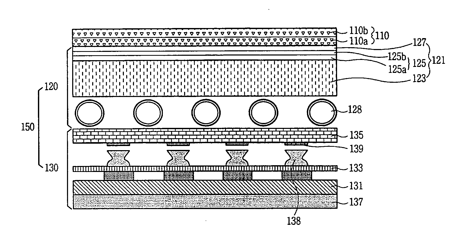
[0027]FIG. 1 shows an exemplary cross-sectional view of a liquid crystal display device in accordance with an embodiment of the present invention. Referring to FIG. 1, the LCD device includes a liquid crystal panel 110 and a backlight unit 150 for supplying light to the liquid crystal panel 110. The liquid crystal panel 110 includes a thin film transistor (TFT) array substrate 110a and a color filter substrate 110b attached to each other. A liquid crystal layer (not shown) is provided between the TFT array substrate 110a and the color filter substrate 110b.

[0028] Gate lines (not shown) are arranged in a first direction on the TFT array substrate 110a. Data lines vertically cross the gate lines to define a matrix of pixel regions on the TFT array substrate 110a. A switching device is provided at each pixel region. Red, green and blue color filter layers, also not shown, are formed on the color filter substrate to correspond with the pixel regions. A black matrix (not shown) is also ...


PUM


Abstract

A backlight unit for a liquid crystal display device includes a first light-emitting unit having first and second passive light-emitting lamps; a second light-emitting unit having a plurality of self light-emitting lamps; and a light guide disposed between the first and second light-emitting units guiding an incident light from the second light-emitting unit to the first light-emitting unit.

Description

[0001] The present invention claims the benefit of Korean Patent Application No. 10-2004-118366 filed in Korea on Dec. 31, 2004, which is hereby incorporated by reference in its entirety. BACKGROUND OF THE INVENTION [0002] 1. Field of the Invention [0003] The present invention relates to a liquid crystal display (LCD) device and, more particularly, to a backlight unit for an LCD device. [0004] 2. Discussion of the Related Art [0005] In general, an LCD device includes a thin film transistor (TFT) array substrate, a color filer substrate, a liquid crystal display panel, a driving unit for driving the liquid crystal panel, and a backlight unit for supplying light to the liquid crystal panel. The thin film transistor (TFT) array substrate and the color filer substrate face each other. The liquid crystal display panel includes a first substrate, a second substrate, and a liquid crystal layer formed between the first and second substrates. [0006] The TFT array substrate includes a plurali...

Claims


Application Information

Patent Timeline
IPC IPC(8): F21V7/04
CPCG02F1/133603G02F1/133604G02F1/133609G02F1/133611G02F1/1335
Inventor PARK, HEE-JEONG
Owner LG DISPLAY CO LTD
Why Eureka
Try Eureka