Hydrodynamic bearing motor

a technology of bearing motors and bearings, applied in sliding contact bearings, record information storage, instruments, etc., can solve the problems of oil trapped in capillary seals, adversely affecting the drive's performance, and pressure difference between upper and lower journal bearings, so as to prevent oil leakage, improve driving characteristics, and prevent oil leakage

Inactive Publication Date: 2006-07-06
G&W TECH
View PDF12 Cites 13 Cited by
  • Summary
  • Abstract
  • Description
  • Claims
  • Application Information

AI Technical Summary

Benefits of technology

[0025] The hydrodynamic bearing motor of the present invention allow air bubbles generated during operation and expanding due to internal heat to be discharged into the atmosphere through the discharge hole, thus preventing leakage of oil while improving driving characteristics by balancing the pressure between the upper and lower journal bearings. Furthermore, when the motor stops operating, the capillary seals serve to prevent leakage of oil. The pressure balancing hole also prevents leakage of oil by smoothly discharging the air bubbles. Because the capillary seals can be used to check the amount of injected oil, an accurate amount of oil can be injected.

Problems solved by technology

Commonly used ball bearings can adversely affect the drive's performance because they generate irregular vibrations, large noise, and have high resonance frequencies caused by bearing defects.
However, one drawback of the hydrodynamic bearing structure is that oil trapped in the capillary seals 150 and 151 or retained in the clearances may escape when air bubbles, generated when the motor operates and the internal temperature thereof increases due to heat generated by friction or an operation of an electromagnetic element, expand and are discharged into the air.
Another drawback is that a pressure difference occurs between upper and lower journal bearings 134 due to air bubbles generated at the journal bearings 134 defined between the inner sleeve 194 and the shaft 114.
Finally, another drawback is that it is difficult to provide sufficient journal bearing length because the upper and lower capillary seals 150 and 151 are located at the top and bottom portions of the shaft 114, respectively.

Method used


Image

  • Hydrodynamic bearing motor
  • Hydrodynamic bearing motor
  • Hydrodynamic bearing motor

Examples


Embodiment Construction

[0033] The present invention will now be described more fully with reference to the accompanying drawings, in which exemplary embodiments of the invention are shown.

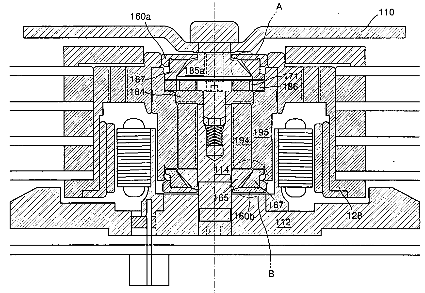
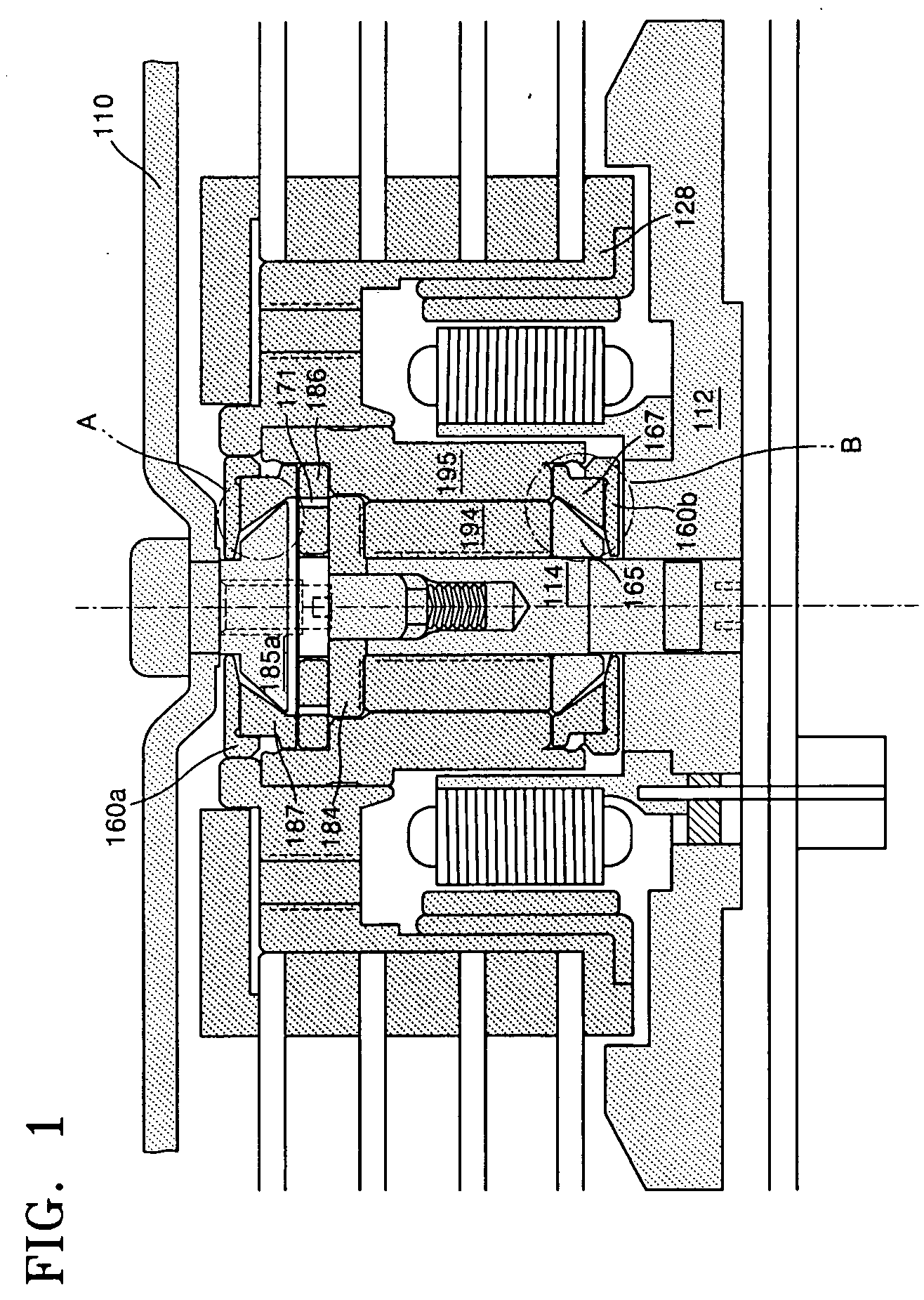
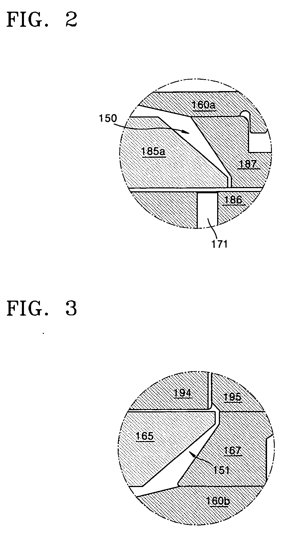
[0034] A hydrodynamic bearing motor according to the present invention prevents leakage of oil due to a capillary action when not operating. When operating, the hydrodynamic bearing motor prevents oil from leaking due to expanded air bubbles while balancing a pressure between upper / lower bearings by smoothly discharging the air bubbles generated at the upper / lower bearings.

[0035] The hydrodynamic bearing motor of the present invention also provides sufficient journal bearing length compared to other motors of the same size, thus allowing a stable operation.

[0036] Referring to FIGS. 4-7, a hydrodynamic bearing motor according to an embodiment of the present invention has a structure in which a hydrodynamic bearing is formed in an oil gap between a rotor and a fixed stator to rotatably support the rotor and oil grooves ...


PUM


Abstract

Provided is a hydrodynamic bearing motor. The hydrodynamic bearing motor, wherein oil journal bearings are formed between a shaft and a sleeve, includes: an upper thrust cover that is fitted over a top portion of the shaft and has an annular rib; a fixture that is secured to a bottom portion of the shaft and has a receiving rib; an upper capillary seal that is defined between an outer circumference of the top portion of the sleeve and the annular rib and retains oil by capillary action; and a lower capillary seal that is defined between an outer circumference of the bottom portion of the sleeve and an inner circumference of the receiving rib and retains oil by capillary action. The hydrodynamic bearing motor provides improved operating characteristics by preventing leakage of oil despite expansion of air bubbles and balancing the pressure between bearings and has improved driving characteristics due to a sufficient journal bearing length.

Description

CROSS-REFERENCE TO RELATED PATENT APPLICATION [0001] This application claims the benefit of Korean Patent Application No. 10-2005-0000074, filed on Jan. 3, 2005, in the Korean Intellectual Property Office, the disclosure of which is incorporated herein in its entirety by reference. BACKGROUND OF THE INVENTION [0002] 1. Field of the Invention [0003] The present invention relates to a hydrodynamic bearing motor, and more particularly, to a hydrodynamic bearing motor having improved operating characteristics, by preventing leakage of oil despite expansion of air bubbles and balancing the pressure between bearings, and improved driving characteristics, by providing sufficient journal bearing length. [0004] 2. Description of the Related Art [0005] To improve the performance of computer hard disk drives various design techniques to achieve higher track density, reduced noise level, and better stability against external factors such as shocks and vibrations must be used. [0006] Commonly us...

Claims


Application Information

Patent Timeline
Patent Type & Authority Applications(United States)
IPC IPC(8): F16C32/06
CPCF16C17/107F16C33/103F16C33/107G11B19/2018H02K7/086F16C2370/12E05B63/22E05B9/02
Inventor KIM, SANG UK
Owner G&W TECH
Why Eureka
Try Eureka