
Combination labyrinth and lip seal for idler rollers

a technology of idler rollers and labyrinths, which is applied in the direction of mechanical equipment, engine components, transportation and packaging, etc., can solve the problems of reducing the load rating of bearings, increasing shaft defection, and reducing bearing li

Inactive Publication Date: 2006-07-06
FMC TECH INC
View PDF26 Cites 25 Cited by
  • Summary
  • Abstract
  • Description
  • Claims
  • Application Information

AI Technical Summary

Benefits of technology

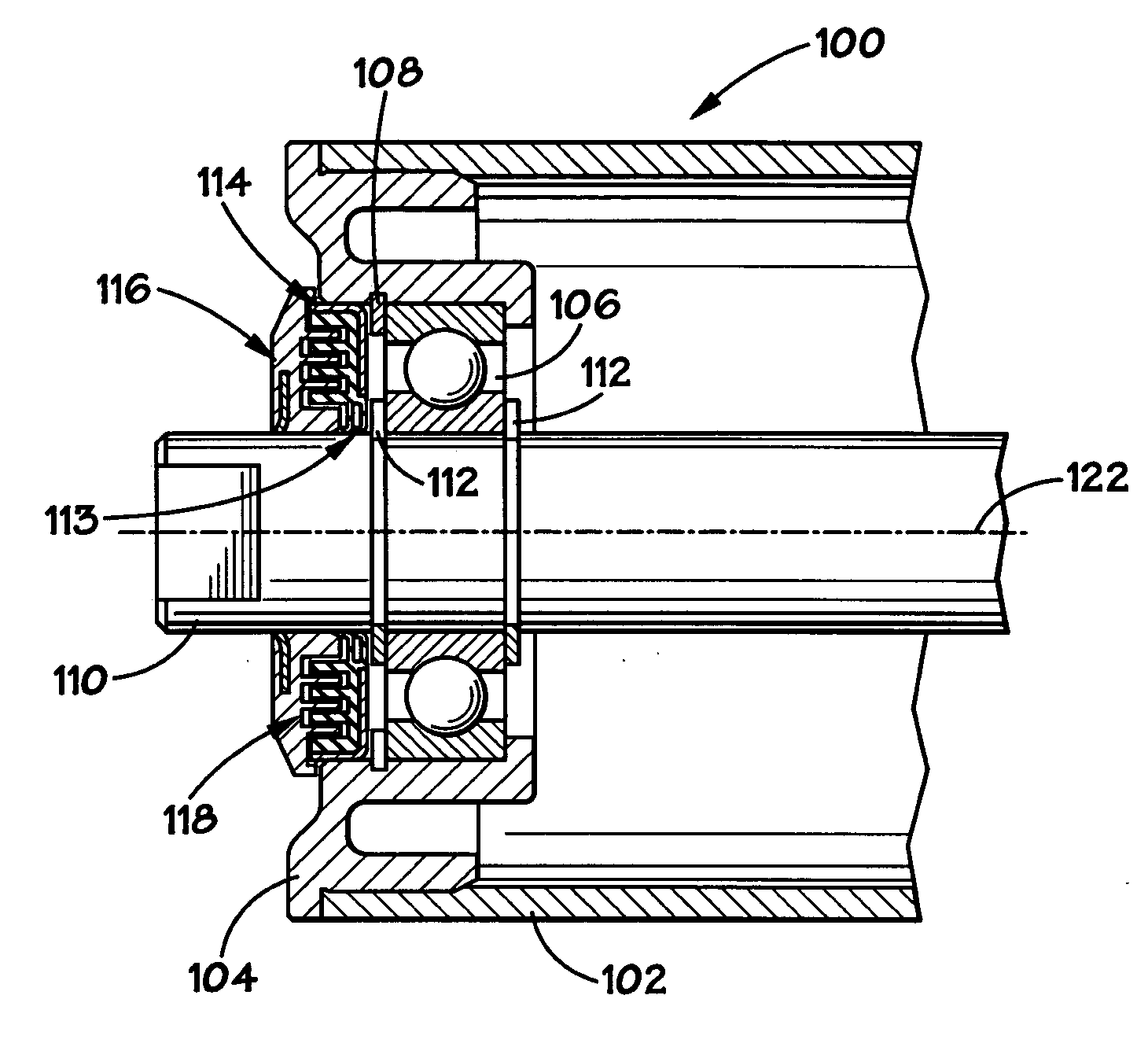
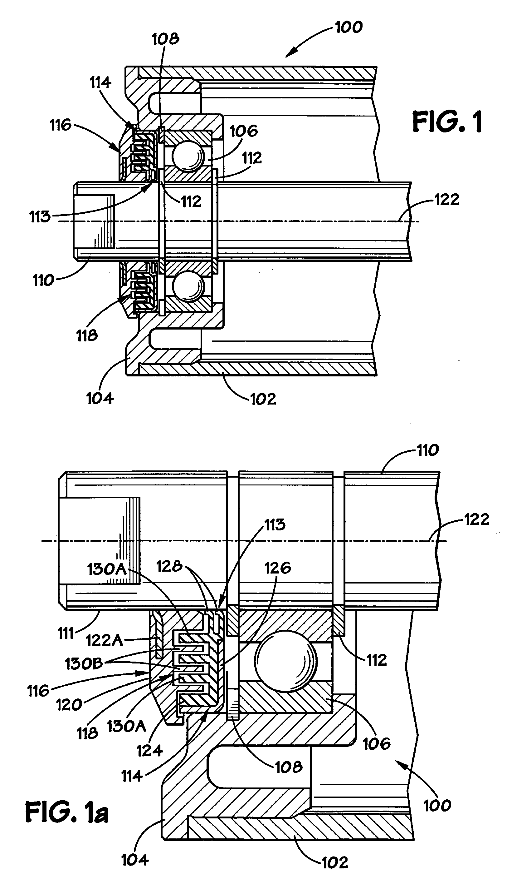
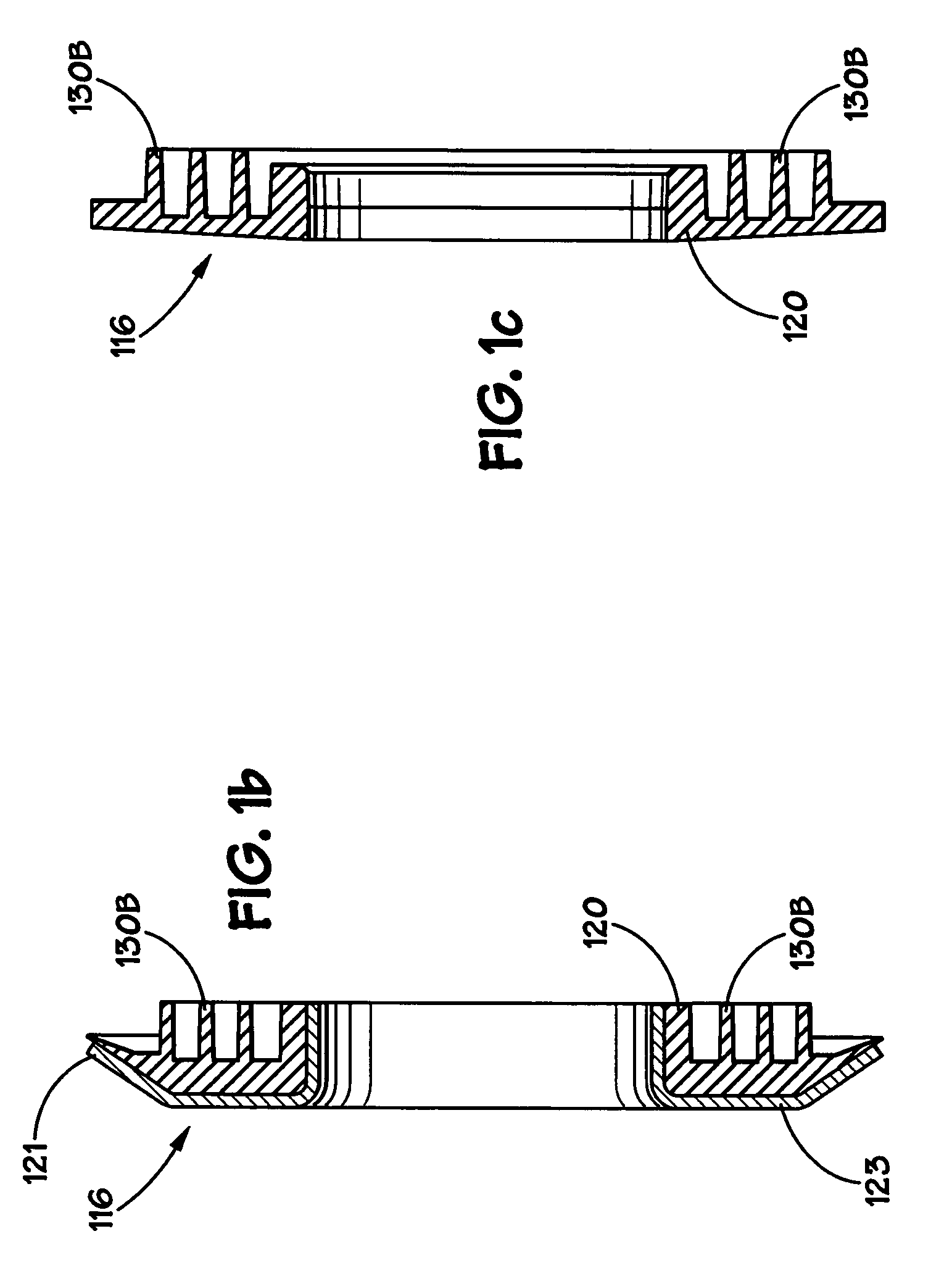
[0013] In one very specific embodiment, the inner labyrinth member further includes two radially extending lip seals that contact the outside diameter of the roller shaft. The dual lip seals provide an additional barrier to the ingress of contaminants. The combination of a labyrinth and a shaft seal in a single member provides many advantages. This type of seal has particular utility in harsh, abrasive environments, such as the above-mentioned tar sand mines, and it may be employed in other environments and in other bearing or roller types.

Problems solved by technology

This increases the leverage distance from the bearings to the shaft supports, which causes increased shaft defection and reduced bearing life.
This shaft deflection diminishes the load rating of the bearing, and consequently causes the idler roller to have a smaller load rating.
However, there is a limit to how much the bearing can be moved outward on the shaft to be closer to the shaft supports to reduce the shaft deflection.
Thus, a problem to be solved is to develop a very thin seal in order to allow the bearings to be moved farther outboard, i.e., closer to the supports.
The environment in which these rollers operate is very harsh, and abrasive material has a tendency to work its way inward through the seals of the rollers, eventually causing catastrophic failure of the rollers.
However, this liquid spray poses an additional risk of failure of the seal elements.

Method used


Image

  • Combination labyrinth and lip seal for idler rollers
  • Combination labyrinth and lip seal for idler rollers
  • Combination labyrinth and lip seal for idler rollers

Examples


Embodiment Construction

[0030] Illustrative embodiments of the invention are described below. In the interest of clarity, not all features of an actual implementation are described in this specification. It will of course be appreciated that in the development of any such actual embodiment, numerous implementation-specific decisions must be made to achieve the developers' specific goals, such as compliance with system-related and business-related constraints, which will vary from one implementation to another. Moreover, it will be appreciated that such a development effort might be complex and time-consuming, but would nevertheless be a routine undertaking for those of ordinary skill in the art having the benefit of this disclosure.

[0031] The present invention will now be described with reference to the attached figures. The words and phrases used herein should be understood and interpreted to have a meaning consistent with the understanding of those words and phrases by those skilled in the relevant art....


PUM


Abstract

An idler roller is disclosed which includes a non-rotating shaft, a roller shell positioned around the non-rotating shaft and a bearing assembly proximate each end of the roller shell. The bearing assembly includes an outer labyrinth member and an inner labyrinth member having an integrally formed shaft seal, wherein the inner and outer labyrinth members define a labyrinth seal and the integrally formed shaft seal sealingly engages an outer surface of the non-rotating shaft.

Description

CROSS-REFERENCE TO RELATED APPLICATIONS [0001] The present application claims priority to U.S. Provisional Patent Application Ser. No. 60 / 623,508 filed Oct. 29, 2004, the entire contents of which is specifically incorporated herein by reference in its entirety.BACKGROUND OF THE INVENTION [0002] 1. Field of the Invention [0003] The present invention relates to a bearing seal assembly for idler rollers, and, more specifically, to a bearing seal assembly for idler rollers for bulk material belt conveyors. An example of this type of belt conveyor system is described in U.S. Pat. No. 6,516,942, the entirely of which is hereby incorporated herein by reference for all purposes. [0004] 2. Description of the Related Art [0005] Typical idler rollers include seal components that protect the bearing from the ingress of contaminants. The traditional location for these seal components is adjacent to the bearings within the same bore between the bearings and the outside environment. The thickness ...

Claims


Application Information

Patent Timeline
Patent Type & Authority Applications(United States)
IPC IPC(8): F16C33/80
CPCF16C33/80F16J15/4478F16C13/022F16C19/06F16C2326/58
Inventor HARWOOD, WILLIAM B.GUSMUS, THOMAS M.SEGURA, ANGEL I.BAIRD, RANDY K.KERSHAW, ROBERT A.
Owner FMC TECH INC
Learn More