
System and method of time-slotted optical burst switching

a time-slotted optical and burst switching technology, applied in data switching networks, multiplex communication, loop networks, etc., can solve problems such as difficulty in related art time-slotted obs networks, data burst loss frequently occurring, and increase costs, so as to minimize the delay of data burst

Inactive Publication Date: 2006-07-06
SAMSUNG ELECTRONICS CO LTD
View PDF7 Cites 10 Cited by
  • Summary
  • Abstract
  • Description
  • Claims
  • Application Information

AI Technical Summary

Benefits of technology

[0024] According to an aspect of the present invention, there is provided system and method of time-slotted optical burst switching for transmitting a data burst transmitted in an optical burst switching network to a destination node while minimizing a delay of the data burst using a constant bit rate (CBR) and a variable bit rate (VBR) is provided.

Problems solved by technology

Generally, the optical fiber additionally requires a photoelectric converter for converting an optical signal into an electrical signal and an electrooptic converter for converting an electrical signal into an optical signal, which results in an increased cost.
However, since the packet size is variable in the related art optical burst switching scheme, data burst loss frequently occurs due to a contention in the optical switch.
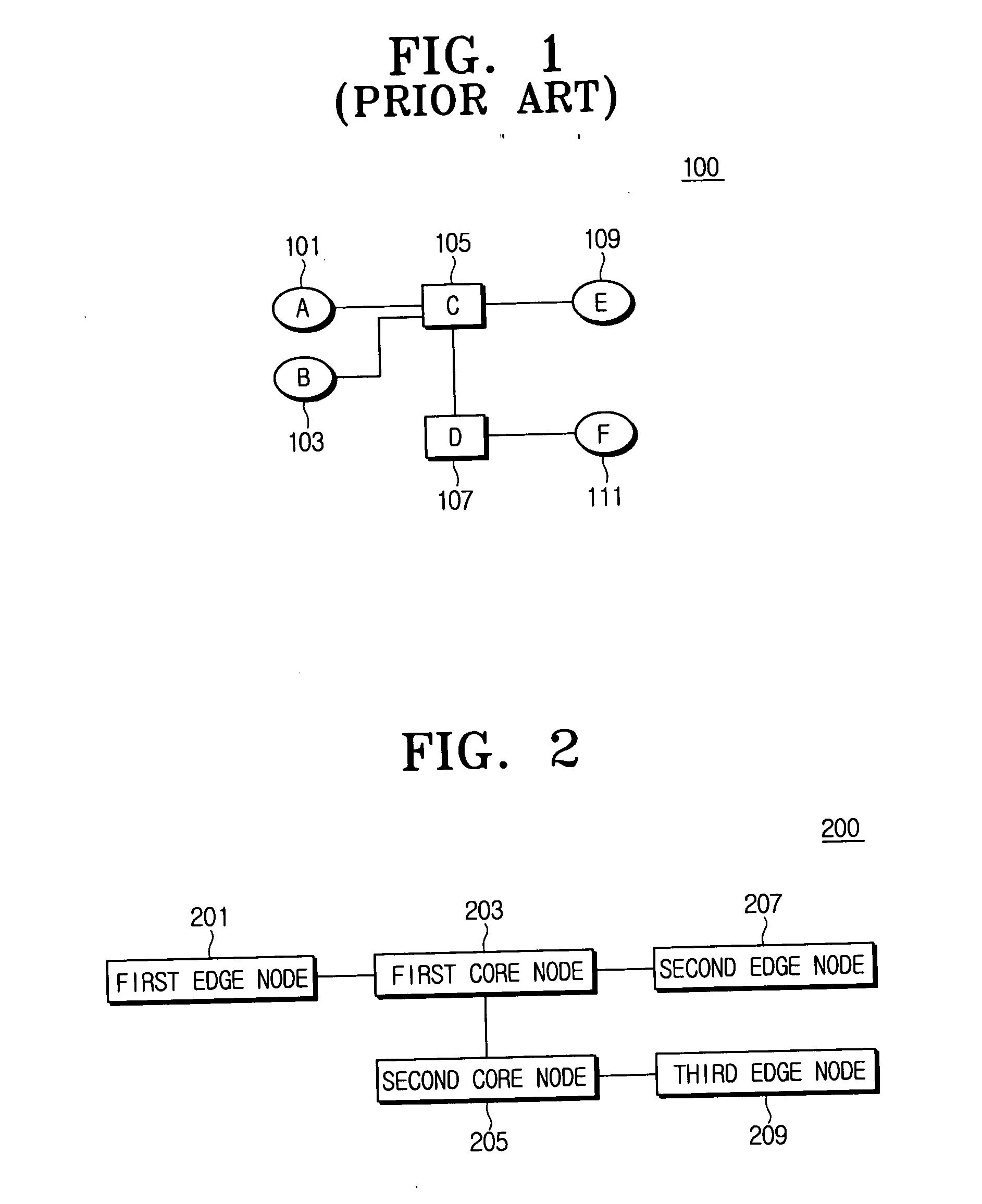
However, there are difficulties in that the time-slotted OBS network 100 deals with services of a constant bit rate (CBR) and a variable bit rate (VBR).
As for services of the constant bit rate, the related art time-slotted OBS network has a difficulty since the data burst is generated and the burst control packet is transmitted.
That is, since even the burst packet that is arrived at node A 101 and formed in the constant bit rate can be transmitted after the burst control packet is transmitted and then a predetermined time is lapsed, a delay inevitably occurs.

Method used

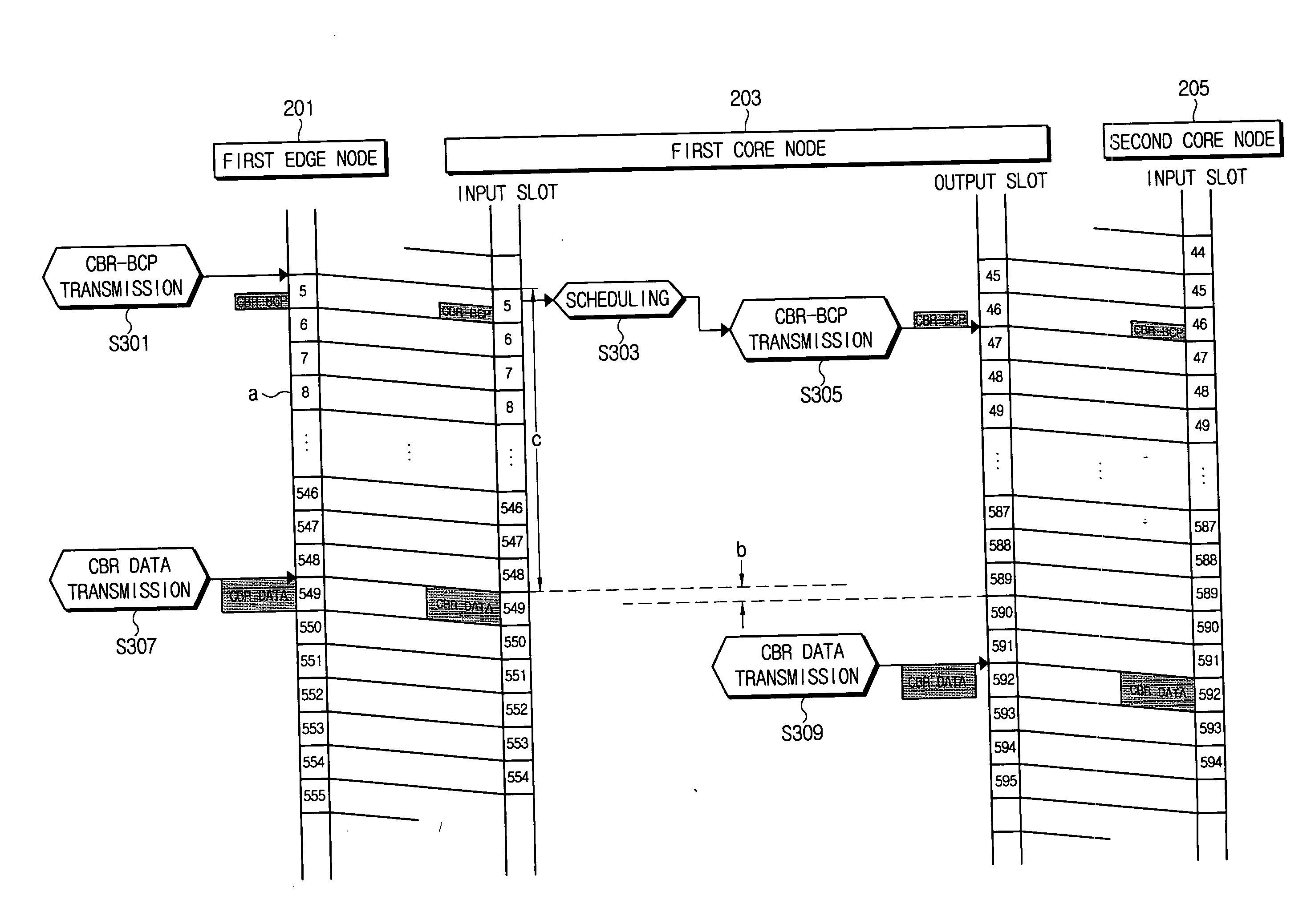
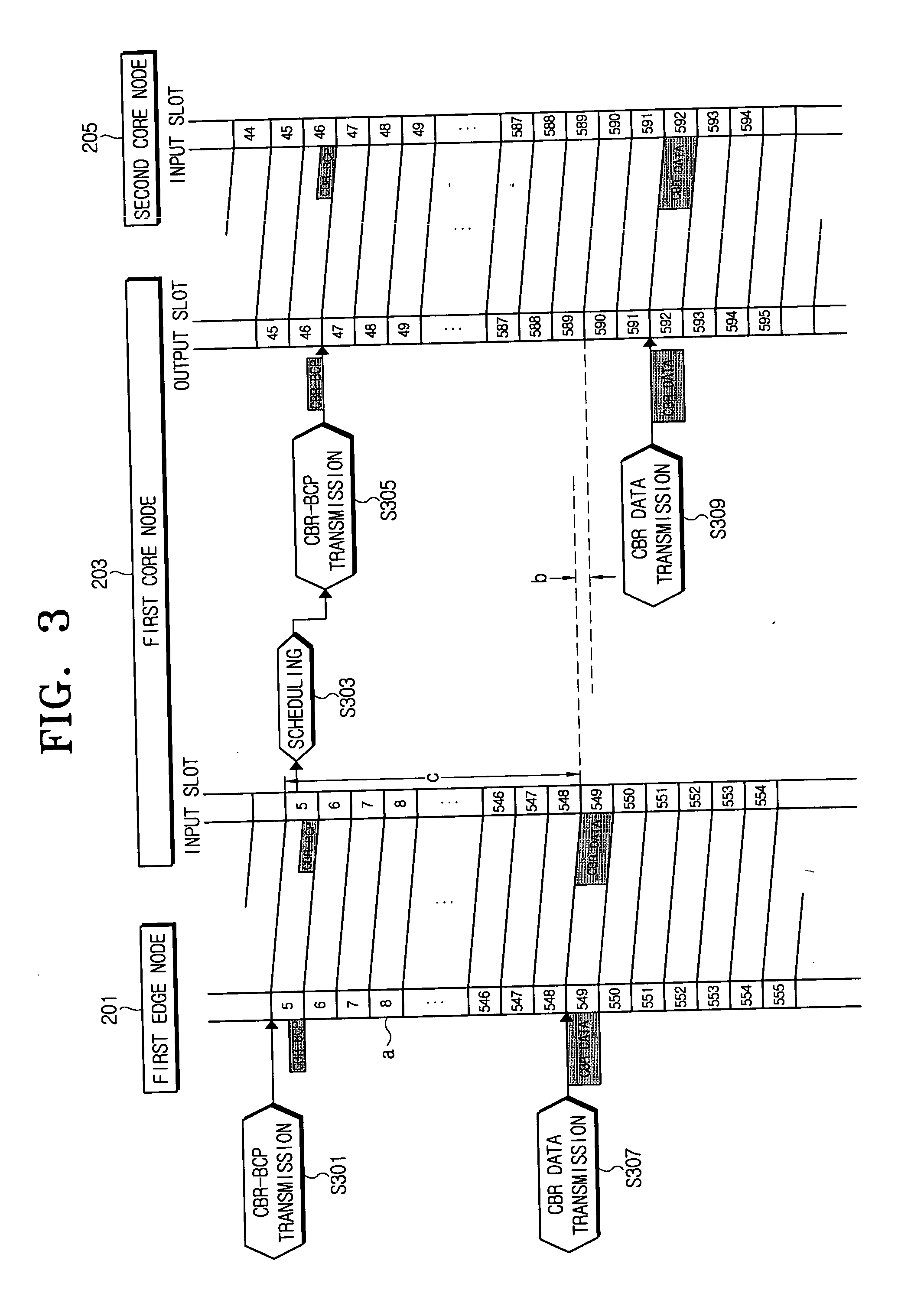

Image

  • System and method of time-slotted optical burst switching
  • System and method of time-slotted optical burst switching
  • System and method of time-slotted optical burst switching

Examples


Embodiment Construction

[0046] Exemplary embodiments will be described in greater detail with reference to the accompanying drawings.

[0047]FIG. 2 is a block diagram showing a time-slotted optical burst switching system in accordance with the exemplary embodiment. A time-slotted optical burst switching (TS OBS) system 200 forms an optical network, including at least one of edge nodes and at least one of core nodes. FIG. 2 shows the first to third edge nodes 201, 207 and 209 representing edge nodes, and first and second core nodes 203 and 205 representing core nodes.

[0048] The system 200 supports the time-slotted optical burst switching, and provides a data transmission service for a constant bit rate and a variable bit rate. Further, it can support a wavelength division multiplexing (WDM) transmission scheme and a dense wavelength division multiplexing (DWDM) transmission scheme.

[0049] The first to third edge nodes 201, 207 and 209 respectively generate a data burst packet and a burst control packet (BCP...


PUM


Abstract

A time-slotted optical burst switching system and method therefor can support data transmissions for a constant bit rate (CBR) and at a variable bit rate (VBR) and improves a data transmission method at an edge node and a core node. Accordingly, it is possible to perform a data service for the constant bit rate and for a variable bit rate and to substantially prevent a delay due to a scheduling for a slot assignment at the core node by transmitting a burst control packet before the data burst to be transmitted at the edge node is generated in case of transmitting the data burst at the constant bit rate.

Description

[0001] This application claims priority from Korean Patent Application No. 2004-117773, filed on Dec. 31, 2004, the entire content of which is incorporated herein by reference. BACKGROUND OF THE INVENTION [0002] 1. Technical Field [0003] Systems and methods consistent with the present invention relate to time-slotted optical burst switching for smoothly supporting a data transmission service for a constant bit rate and a variable bit rate in an optical burst switching network. [0004] 2. Related Art [0005] Optical communication is superior to other communication methods due to its availability in a broad frequency region. Assuming that loss per unit distance is 2 dB / km, the bandwidth is about 130 THz (100 nm) for optical communication. Among such a broad transmissible region, a current optical communication technology has used only a single channel having several hundreds MHz to several GHz bands near 1.3 μm wavelength. [0006] A wavelength division multiplexing transmission scheme is...

Claims


Application Information

Patent Timeline
IPC IPC(8): H04J14/00
CPCH04J14/0227H04J14/0284H04Q11/0066H04Q2011/0064H04Q2011/0084H04J14/0241H04B10/25H04Q11/00
Inventor DEN HOLLANDER, CORNELIS JOHANNISGARNER, GEOFFREY M.
Owner SAMSUNG ELECTRONICS CO LTD
Learn More