Small scale ideal kinetic reactor to evaluate full size industrial catalysts
a kinetic reactor and industrial catalyst technology, applied in the field of material analysis systems, can solve the problems of not being able to achieve ideal displacement conditions, not being able to conduct real flow reaction conditions, and a large amount of catalyst materials, and achieve the effect of fast experiment turnaround and uniform mass transfer
- Summary
- Abstract
- Description
- Claims
- Application Information
AI Technical Summary
Benefits of technology
Problems solved by technology
Method used
Image
Examples
example 1
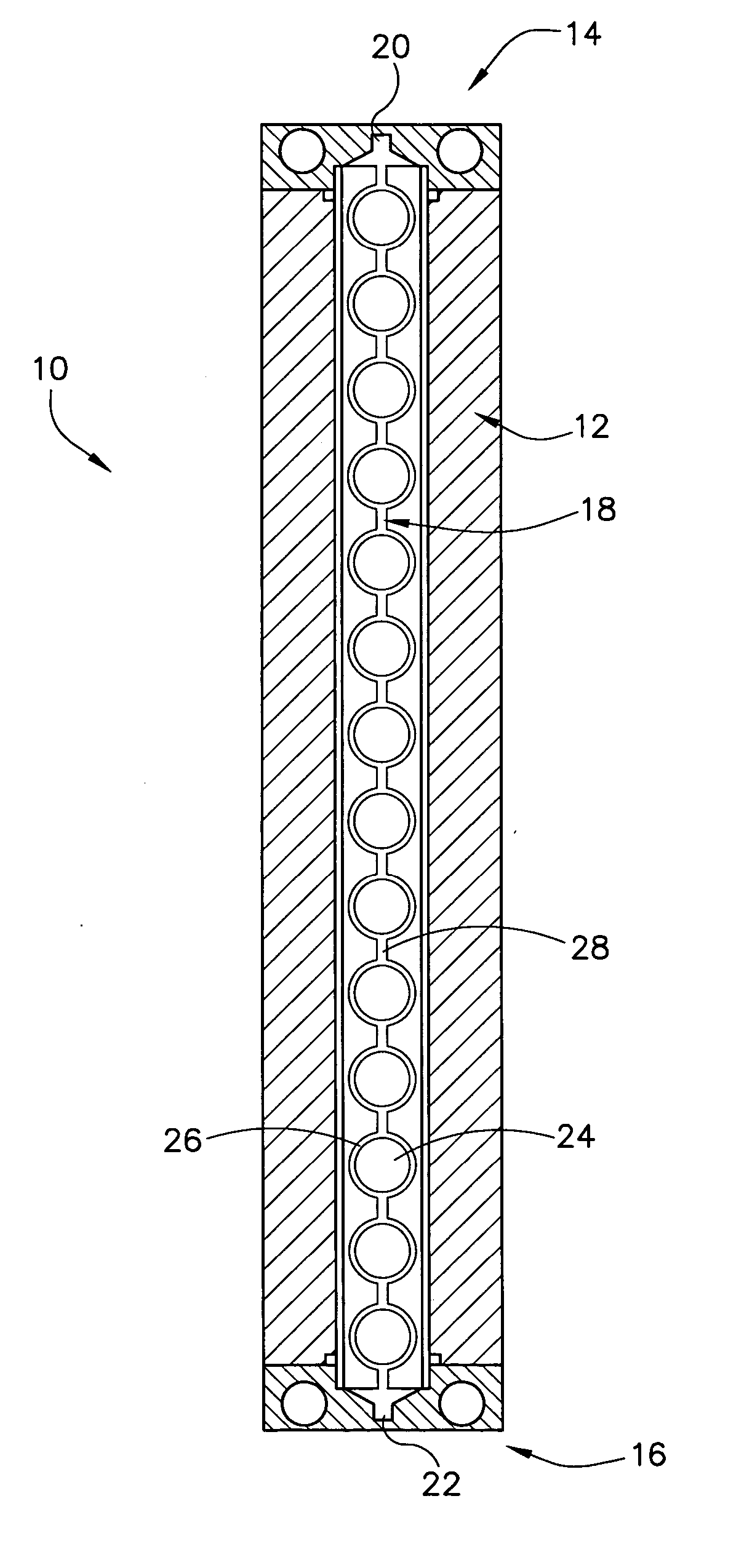
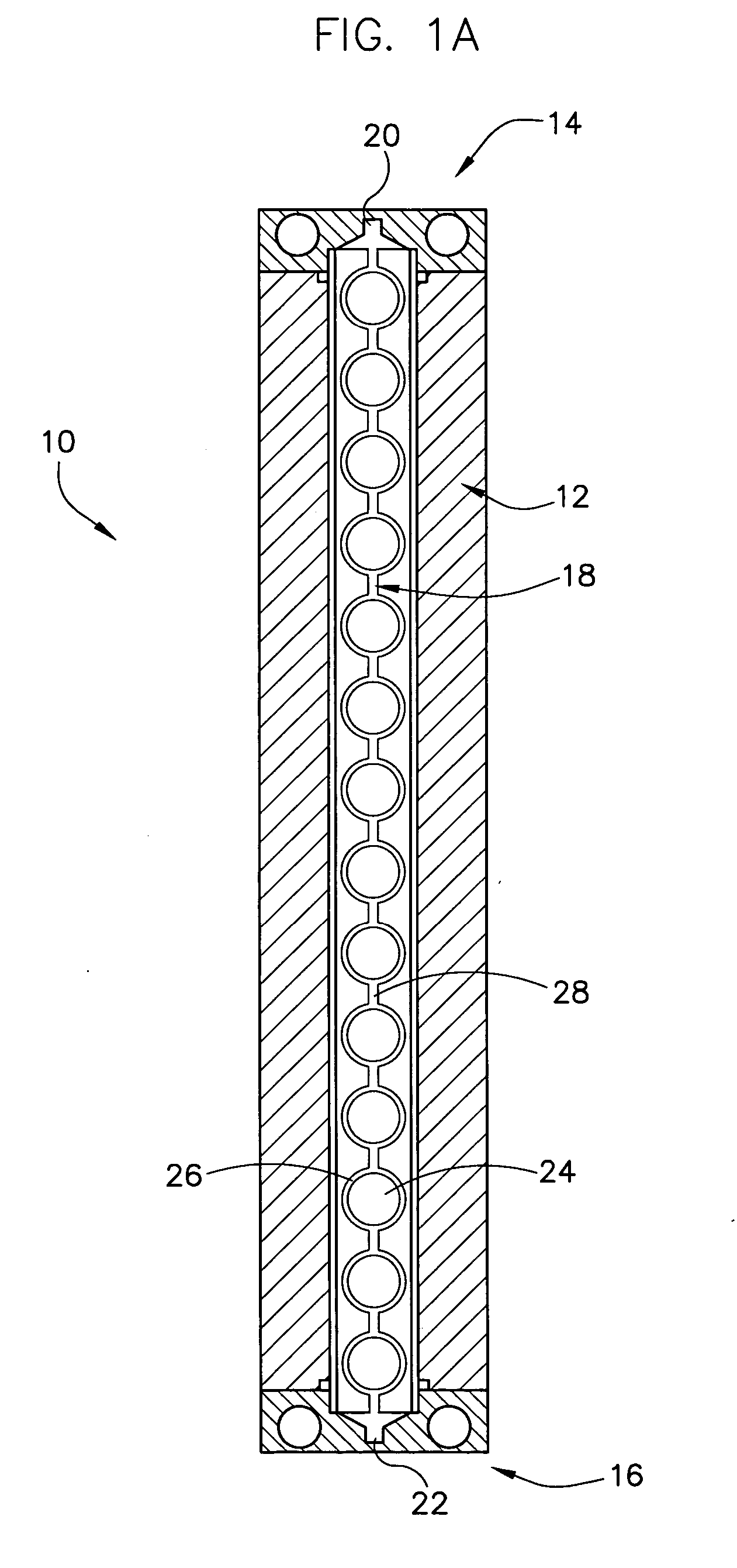
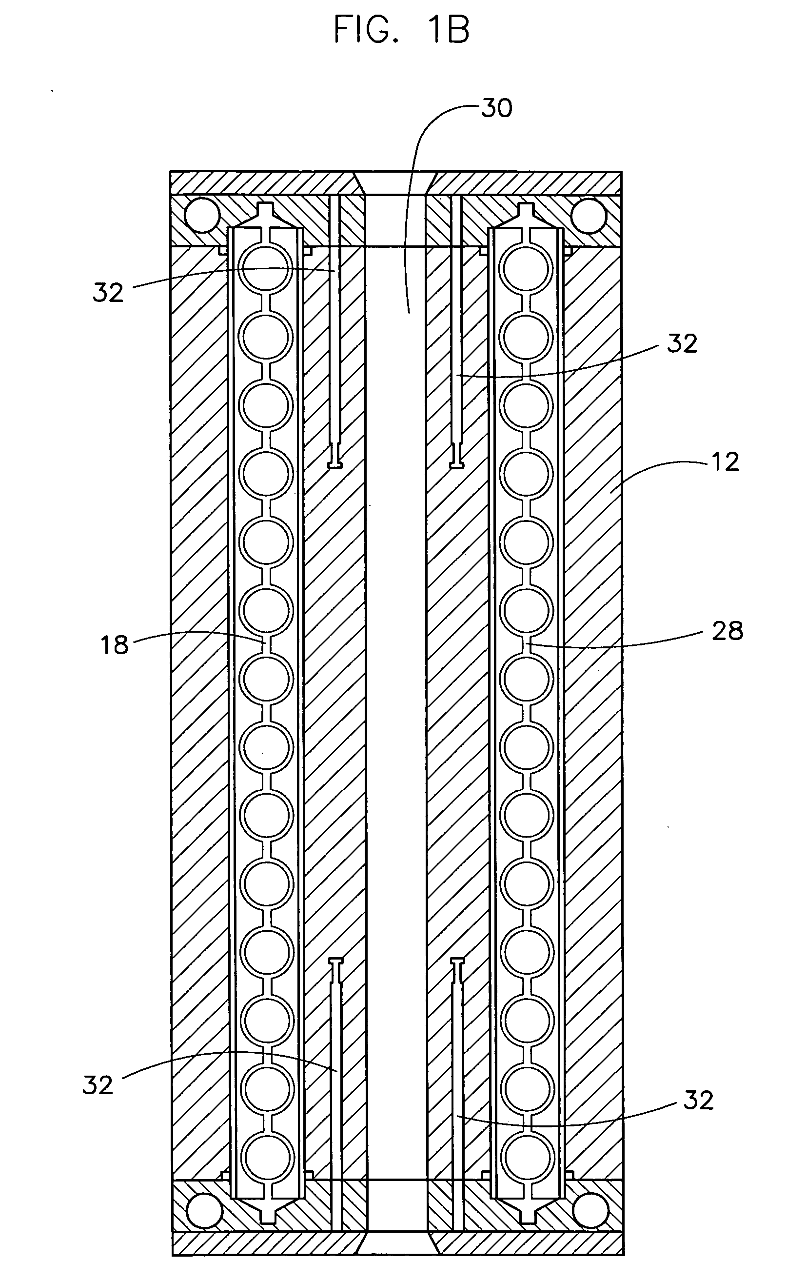
[0077] A modular ball reactor, such as that described above, having 7 mm diameter reaction cells, was used to confirm that the hydrodynamics of the reactor of the present invention perform comparably to a pilot or industrial scale fixed bed reactor. Calculated Peclet numbers for axial dispersion were used as a comparison. Helium gas was initially run through the reactor, and at time=0, the gas was switched to nitrogen. The time it took for the nitrogen to be detected at the outlet of the reactor corresponds to the residence time distribution (RTD) data listed in FIG. 7. the inserts were designed to hold 14 particles. Tests were run on a 28 particle system (using 6 mm glass beads to represent industrial form catalyst particles), using a configuration as shown in FIG. 1C, and on a 56 particle system, using a configuration as shown and described in FIG. 6B.
[0078] Results indicate a Pe=300 (±50) for 28×6 mm Glass Beads (One body) and a Pe=150 (±25) for 56×6 mm Glass Beads (Two bodies) ...
example 2
[0081] In this example, experiments were conducted to determine and compare the residence time distribution (RTD) and velocity profiles in the prior art reactor described by Temkin as shown in FIG. 9A and a modular ball reactor as described above. The reactor 900 shown in FIG. 9A comprises a plurality of beads or catalyst particles 902 located in a tube 904 and spaced apart by inert cylindrical spacers 906.
[0082] The experiments were performed using FLUENT computational fluid dynamics software. Both 2D and 3D simulations were performed on both designs and after validating the 2D results with the 3D results, the 2D models were used to reduce computation time.
[0083] Nitrogen was used as the process gas to model fluid flow and was run at 1 liter / minute. The RTD experiments were performed as step experiments. While the system was at steady state, flow was switched from a tracer nitrogen species (having exactly the same physical properties as nitrogen) to nitrogen and the concentration...
PUM
 Abstract
Description
Claims
Application Information
 - R&D
- Intellectual Property
- Life Sciences
- Materials
- Tech Scout
- Unparalleled Data Quality
- Higher Quality Content
- 60% Fewer Hallucinations
Browse by: Latest US Patents, China's latest patents, Technical Efficacy Thesaurus, Application Domain, Technology Topic, Popular Technical Reports.
© 2025 PatSnap. All rights reserved.Legal|Privacy policy|Modern Slavery Act Transparency Statement|Sitemap|About US| Contact US: help@patsnap.com


