Planetary gear replacement method

a technology of gear mechanism and gear body, which is applied in the direction of gearing details, machine/engine, manufacturing tools, etc., can solve the problems of gear mechanism damage, performance is sometimes difficult to implement, and damage to wind energy systems has become known with remarkable frequency, so as to reduce axial thickness and reduce weight , the effect of less axial thickness

Inactive Publication Date: 2006-07-06
EICKHOFF MASCHFAB
View PDF3 Cites 16 Cited by
  • Summary
  • Abstract
  • Description
  • Claims
  • Application Information

AI Technical Summary

Benefits of technology

[0042] The second cheek piece can have a lesser axial thickness than the first, in order to save weight, since it is primarily needed to center the wheel and does not have to absorb any great forces.
[0043] The pin is preferably provided with a wedge surface on the end, so that it can be introduced into the bores more easily.

Problems solved by technology

This arrangement is a common gear mechanism concept in the wind energy sector, because wind energy gear mechanisms must perform translations of up to 90, and this performance is sometimes difficult to implement with a single planetary stage, given the limited construction space in the gondola.
In recent times, damage to wind energy systems has become known with remarkable frequency, which is possibly attributable to uncertainties in the dimensions and / or method of operation.
The damage relates to the gear mechanisms, among other things, which are fixed in place between rotor and generator, as the core piece of the drive train.
Therefore, the gear mechanisms are exposed to negative influences on all sides.
The consequences are premature fatigue or even total failure of individual components of the gear mechanism such as wheels and bearings.
These cases of damage can be countered by replacement of components of the gear mechanism that are particularly at risk of failure.
However, the replacement of individual components of a wind energy gear mechanism because of its exposed position involves difficulties that increase costs.
The resulting repair costs reach dimensions that make the replacement of components that are at risk of damage or have already been damaged appear uneconomical, in light of the low earnings of a wind energy system.
Such wind energy systems have not become widespread to any noteworthy extent up to now.
Instead, in most cases, older systems have to be repaired, which do not have a sufficiently powerful on-board crane and whose opening in the gondola floor measures at most a square meter, which is by far not enough to pass the gear mechanism through.

Method used


Image

  • Planetary gear replacement method
  • Planetary gear replacement method
  • Planetary gear replacement method

Examples


Embodiment Construction

[0053] The following table indicates the figures in which the individual method steps are shown.

TABLE 1(linking of the characteristicsin the Summary of the Invention with the figures)CharacteristicFIG.1 aa11 ab11 ac11 ad11 ae11 af11 ag11 ba—1 bb2 b1 bc2 c1 bd2 d1 be2 e1 bf—1 bg2 f1 bh2 g1 bi2 h1 bj2 i1 bk—1 bl2 j1 bm2 k1 bn2 l1 bo2 m

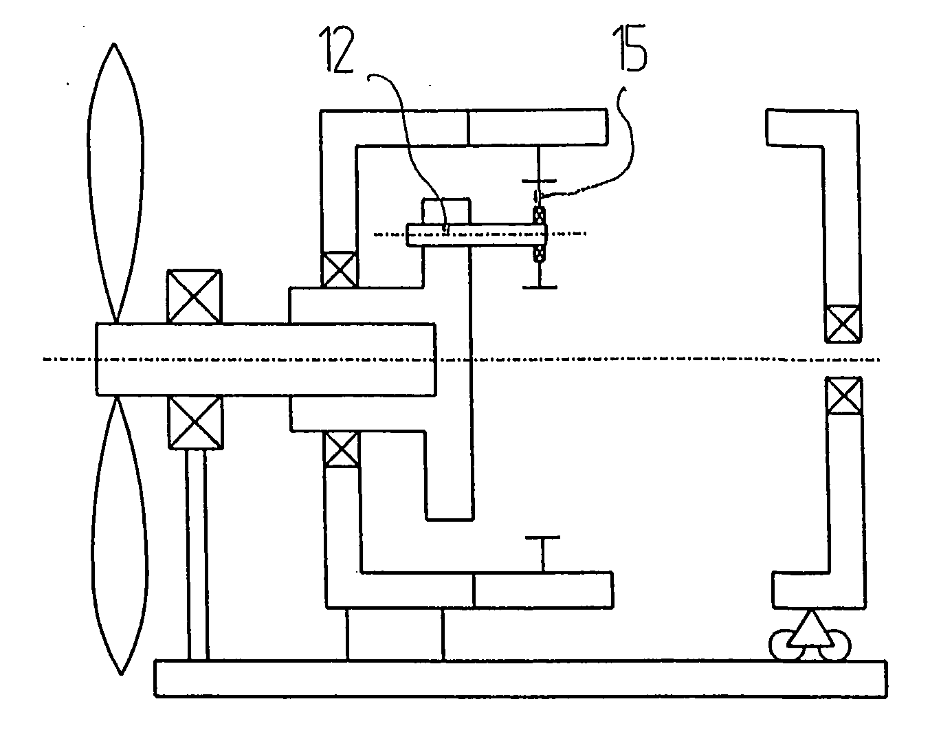
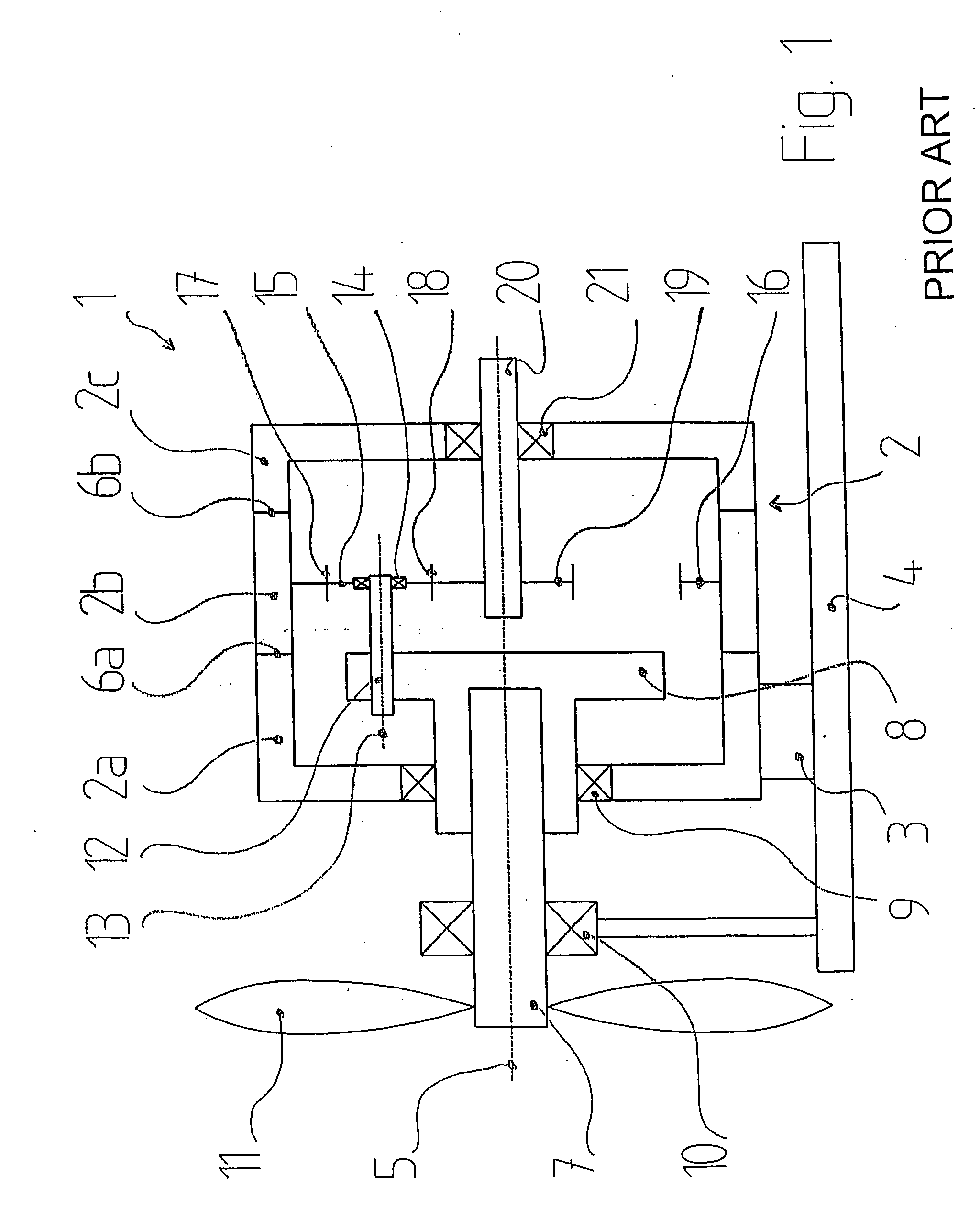
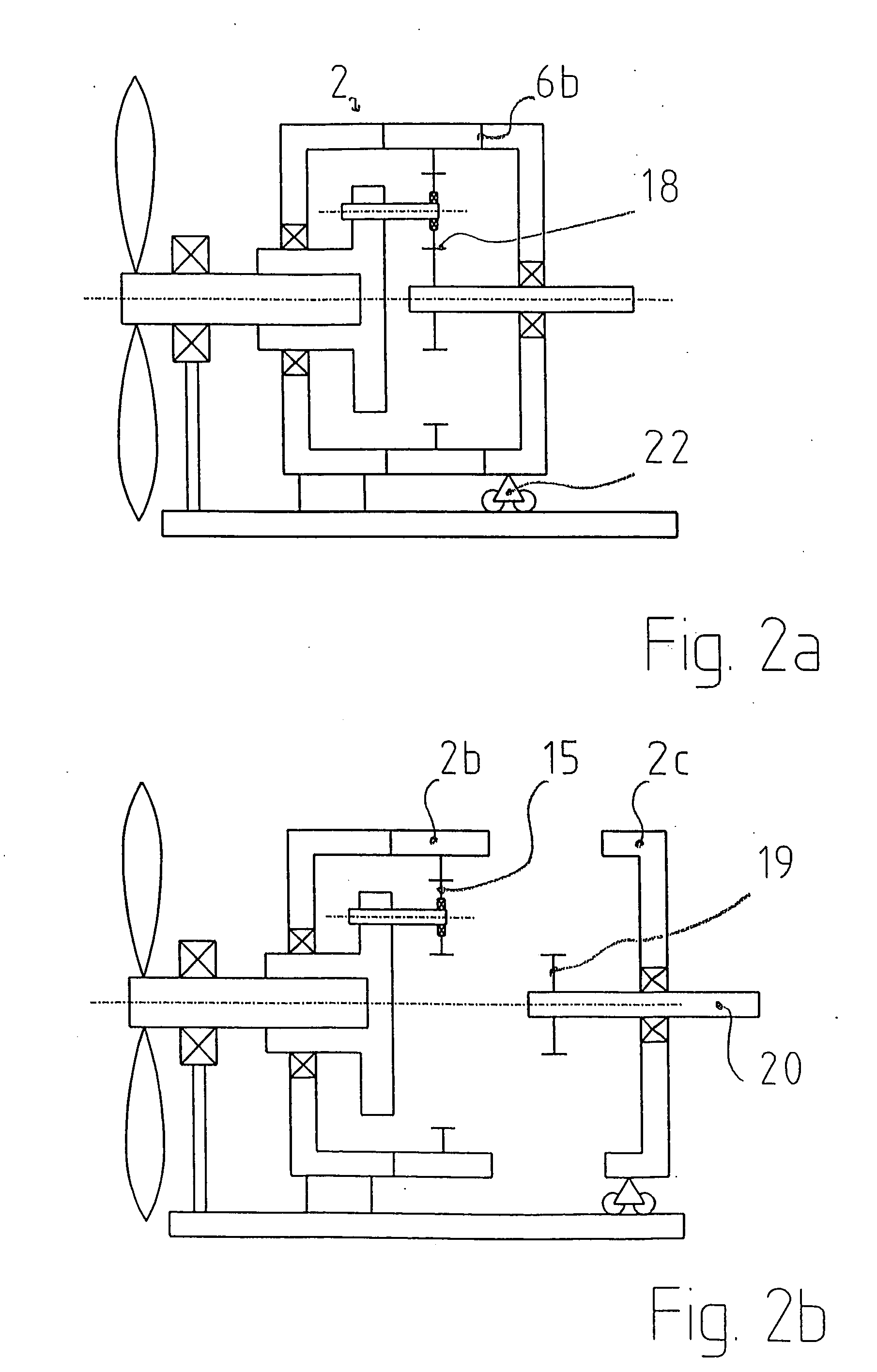
[0054]FIG. 1 shows the fundamental structure of an epicyclic gear mechanism 1 of the type stated initially, which can be used in a wind energy system. It is referred to below in short as gear mechanism 1. Gear mechanism 1 includes a housing 2 that is composed of three sections: a drive-side section 2a, a center section 2b, and a power take-off side section 2c. Drive section 2a is rigidly connected with a machine frame 4 by way of a housing bearing 3. The three sections 2a, 2b, 2c extend along a main axis 5 of gear mechanism 1 and abut two parting planes 6a, 6b oriented normal to main axis 5. The adjacent sections 2a, 2b, 2c, in each instance, are relea...


PUM

PropertyMeasurementUnit
weightsaaaaaaaaaa
axial thicknessaaaaaaaaaa
speedaaaaaaaaaa

Abstract

A method permits replacement of components of existing epicyclic gear mechanisms of a wind energy system without having to lift the gear mechanism down from the gondola. In accordance with the method, the housing is divided up alternately in its first parting plane and in its second parting plane and moved apart. The center section of the housing, which includes the internal geared wheel, always remains connected with an adjacent section and therefore does not have to be moved with a hoist. Access to the components to be replaced is always guaranteed by the special method of opening. An installation bolt is also provided that is particularly suitable for implementing the method.

Description

CROSS REFERENCE TO RELATED APPLICATIONS [0001] Applicants claim priority under 35 U.S.C. §119 of European Application No. 04 031 089.8 filed on Dec. 31, 2004. BACKGROUND OF THE INVENTION [0002] 1. Field of the Invention [0003] The present invention relates to a method for replacing components of an epicyclic gear mechanism that is used particularly in a wind energy system. The epicyclic gear mechanism has a main axis; a housing that is divided by two parting planes into a drive side section, a center section, and a power take-off side section, whereby the three sections of the housing are lined up along the main axis, and whereby the housing can be separated in the parting planes; a pinion cage, which is mounted to rotate about the main axis in the drive side section of the housing and which has at least one planet bolt that extends along a planet axis that is fixed relative to the pinion cage and runs parallel to the main axis; an internal geared wheel that is disposed in the cente...

Claims


Application Information

Patent Timeline
Patent Type & Authority Applications(United States)
IPC IPC(8): F16H57/08
CPCF05B2260/40311F16H57/023F16H57/08F16H57/082F16H2057/02013F16H2057/02078F16H2057/0235F03D15/00F03D80/50Y02E10/72Y10T29/49464Y10T29/49465Y10T29/49718Y10T29/4973Y10T29/49826
Inventor ALBERS, HELMUTAUST, RAINERDOMBROWSKI, WOLFHARDKOWALCZIK, INGONEUFELDER, MARC
Owner EICKHOFF MASCHFAB
Why Eureka
Try Eureka