
On-chip data transmission control apparatus and method

a control apparatus and data technology, applied in the field of on-chip data transmission, can solve problems such as chip-on noise and chip malfunction, and achieve the effect of improving the structure of the existing on-chip data output apparatus and improving an operation characteristic of the chip devi

Inactive Publication Date: 2006-07-06
SK HYNIX INC
View PDF6 Cites 6 Cited by
  • Summary
  • Abstract
  • Description
  • Claims
  • Application Information

AI Technical Summary

Benefits of technology

[0006] It is, therefore, a primary object of the present invention to provide an on-chip data transmission control apparatus and method capable of improving an operation characteristic of a chip device by minimizing an issuance of noise due to transition of data transmitted by an improvement of a structure of the existing on-chip data output apparatus.

Problems solved by technology

This induces a chip-on noise and in turn leads to a malfunctioning of the chip.

Method used


Image

  • On-chip data transmission control apparatus and method
  • On-chip data transmission control apparatus and method
  • On-chip data transmission control apparatus and method

Examples


second embodiment

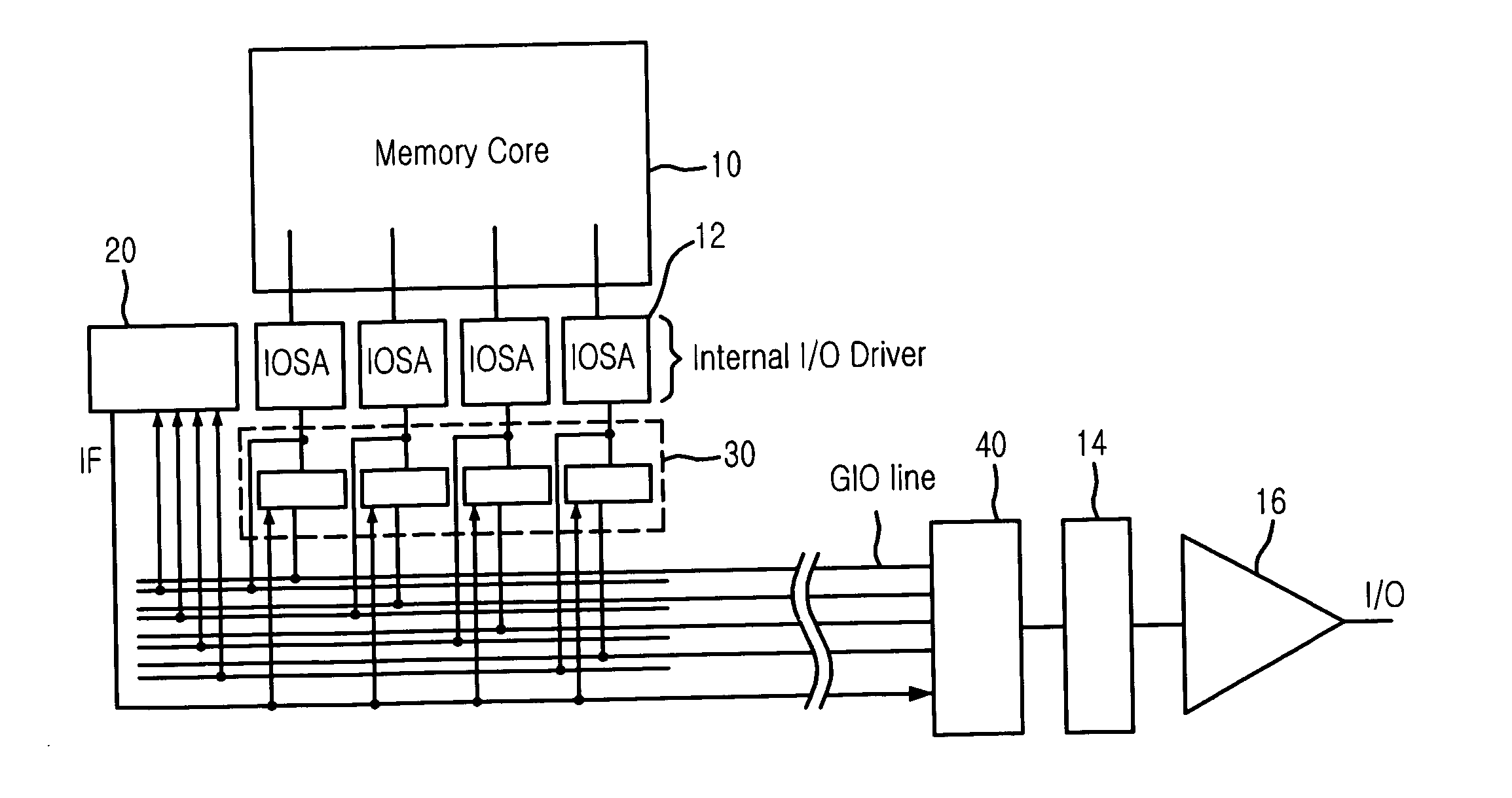
[0082]FIG. 15 is a circuit diagram representing a configuration of an on-chip data transmission control apparatus in accordance with the present invention.

[0083] In this embodiment, although it is shown that the data comparison unit 20 is implemented with only the transition rate calculator 28, it should be noted that other composition elements are the same as those in FIG. 2.

[0084] In case of this embodiment, although it does not compare the current data with the previous data, the inversion flag IF is activated if the number of high level data in the current data is larger than the preset number. In this case, the on-chip noise can be reduced below ½ compared to the prior art since the transition number of the high data and low data becomes equal. This is because a consumption of a supply voltage VDD to charge the GIO line or a discharge of the ground voltage VSS to discharge the GIO line to the ground level is always incurred only below ½ of the total data number.

third embodiment

[0085]FIG. 16 is a circuit diagram representing a configuration of an on-chip data transmission control apparatus in accordance with the present invention.

[0086] In this embodiment, the apparatus comprises a register 60 and a flag driver 70 for storing and outputting the inversion flag IF, instead of removing the second data inversion unit 40 in FIG. 11. That is to say, in order to decrease the number of data being transited on the internal GIO line as well as the number of data being transited on external IO line (not shown), the data inverted in the first data inversion unit 30 is outputted onto the external IO line immediately, without no additional inversion within the data transmission control apparatus.

[0087]FIG. 17 is a circuit diagram showing an embodiment where a data transmission control method of the present invention is applied to a data input device.

[0088] The transmission data transition method in accordance with the present invention may also be applied to an instan...


PUM


Abstract

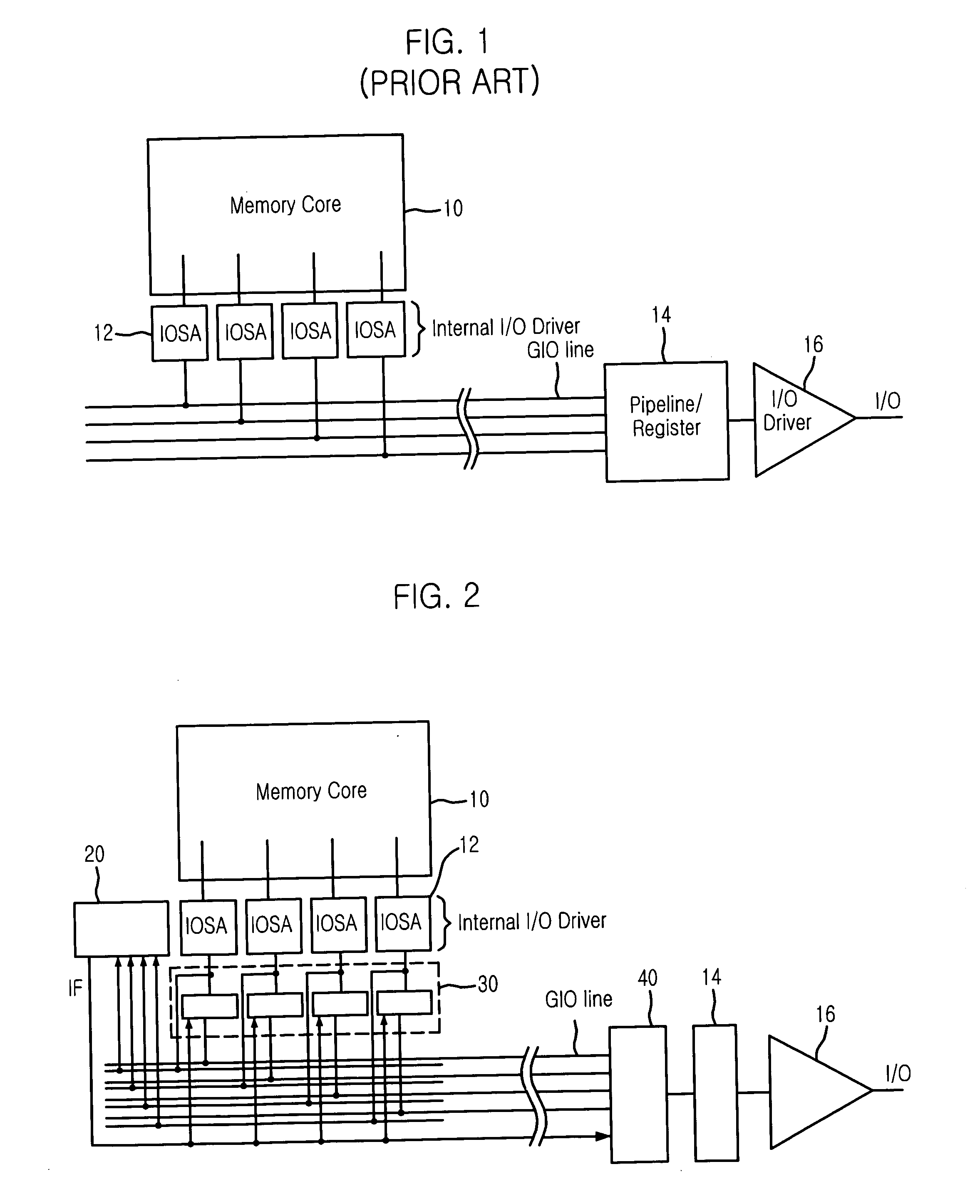
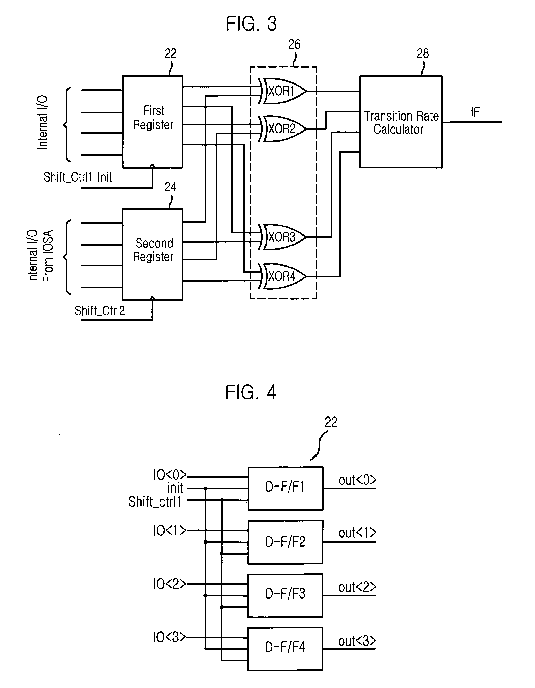
The on-chip data transmission controller comprises a data comparison unit for comparing current data with previous data and issuing an inversion flag if the number of data bits phase-transited is larger than a preset number, a first data inversion unit for inverting a phase of the current data when the inversion flag is activated and providing inverted data onto a data bus, and a second data inversion unit for inverting a phase of the data transmitted via the data bus when the inversion flag is activated and outputting inverted data. Through this controller, an on-chip noise that largely occurs as the number of data to be transmitted increases can be reduced, by decreasing transition number of data inputted via the GIO line, in case of using a multi step pre-patch structure to improve an operation speed of a memory device.

Description

FIELD OF THE INVENTION [0001] The present invention relates to an on-chip data transmission; and more particularly, to an on-chip data transmission control apparatus and method capable of improving an operation characteristic of a chip device by suppressing an issuance of on-chip noise. This is accomplished by inverting, if a rate of data transited (“transition rate”) is higher than a preset rate after sensing a number of data bits phase-transited (“transition number”) in data outputted via a data bus, data to be transmitted and lowering the transition rate. DESCRIPTION OF RELATED ART [0002]FIG. 1 is a circuit diagram showing a configuration of a conventional on-chip data output apparatus. [0003] Specifically, FIG. 1 depicts a configuration of the conventional on-chip data output apparatus that employs one external input / output (I / O) and 4-bit pre-patch. In this structure, the number of I / O substantially necessary for communication with the outside is one and an operation speed of a...

Claims


Application Information

Patent Timeline
IPC IPC(8): G06F11/00G01R31/28
CPCH04L25/4915G11C7/1048G11C7/1051G11C7/22
Inventor LEE, HYUNG-DONGJANG, EUN-JUNG
Owner SK HYNIX INC
Learn More