Control joint

a control joint and joint technology, applied in bridges, bridge structural details, roads, etc., can solve the problems of not being able to accommodate different thicknesses of plaster on the opposing sides of the joint, prior control joint arrangements, etc., to facilitate flexible movement, facilitate flexible movement, facilitate flexible movement

Active Publication Date: 2006-07-13
CLARKWESTERN DIETRICH BUILDING SYST
View PDF93 Cites 31 Cited by
  • Summary
  • Abstract
  • Description
  • Claims
  • Application Information

AI Technical Summary

Benefits of technology

[0012] Another embodiment of the present invention comprises a corner assembly for forming intersecting screed walls for adjacent amounts of plaster. In one embodiment, the corner assembly comprises a first control joint that has a first base portion and a first screed wall that has a first proximal end that protrudes from the first base portion and a first distal end that is remote from the first base portion. The first control joint further has a second base portion and a second screed wall that has a second proximal end that protrudes from the second base portion and a second distal end that is remote from the second base portion. A flexible attachment assembly is attached between the first screed wall and the second screed wall such that the first and second screed walls are in spaced relationship to each other. The flexible attachment assembly facilitates flexible movement between the first and second screed walls. The corner assembly further includes a second control joint that has another first base portion and another first screed wall that has another first proximal end that protrudes from the another first base portion and another first distal end that is remote from the another first base portion. The second control joint further includes another second base portion that has another second screed wall that has another second proximal end that protrudes from the another second base portion and another second distal end that is remote from the another second base portion. Another flexible attachment assembly is attached between the another first screed wall and the another second screed wal

Problems solved by technology

Prior control joint arrangements, however, cannot accommodate d

Method used


Image

  • Control joint
  • Control joint
  • Control joint

Examples


Embodiment Construction

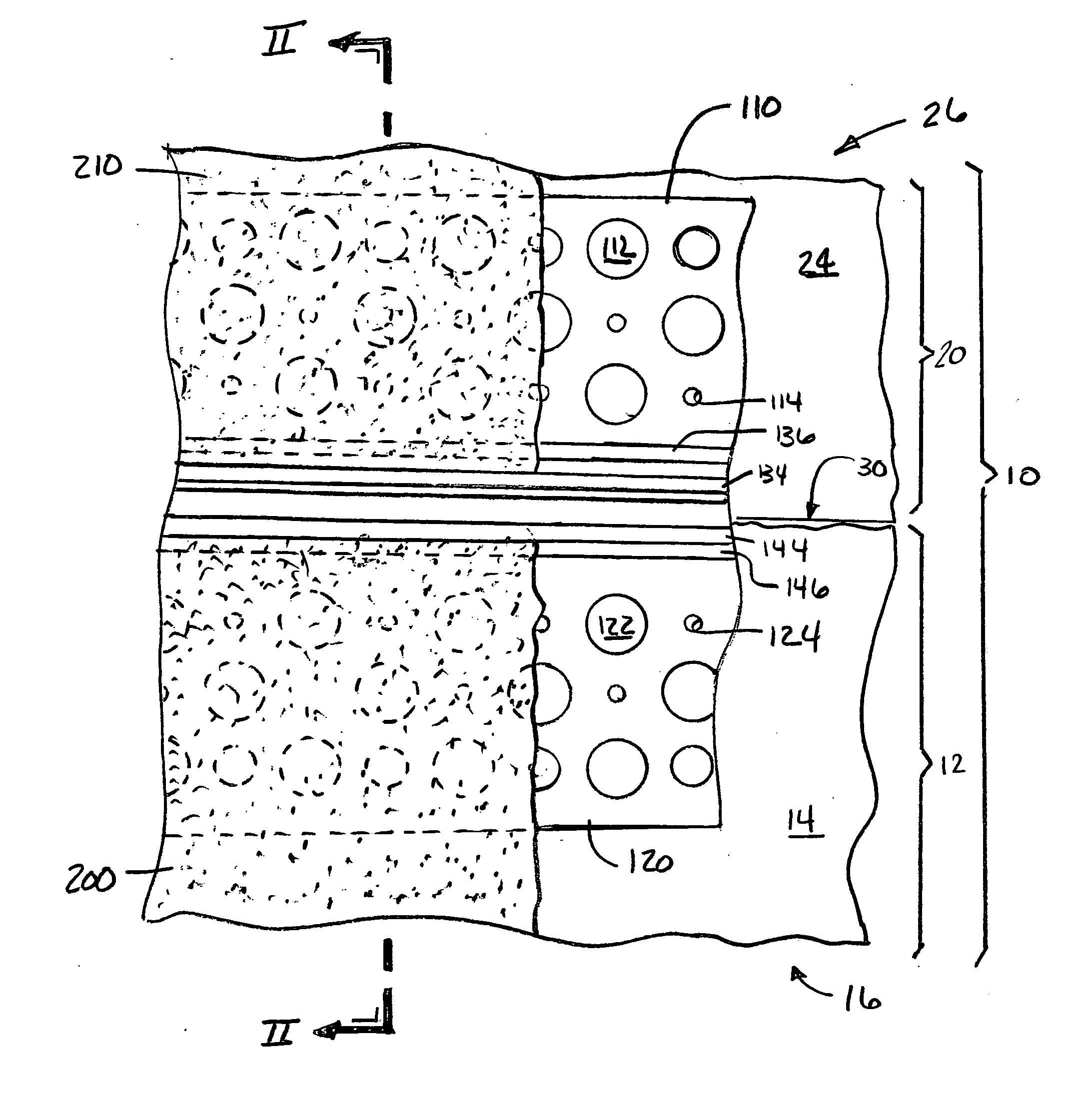
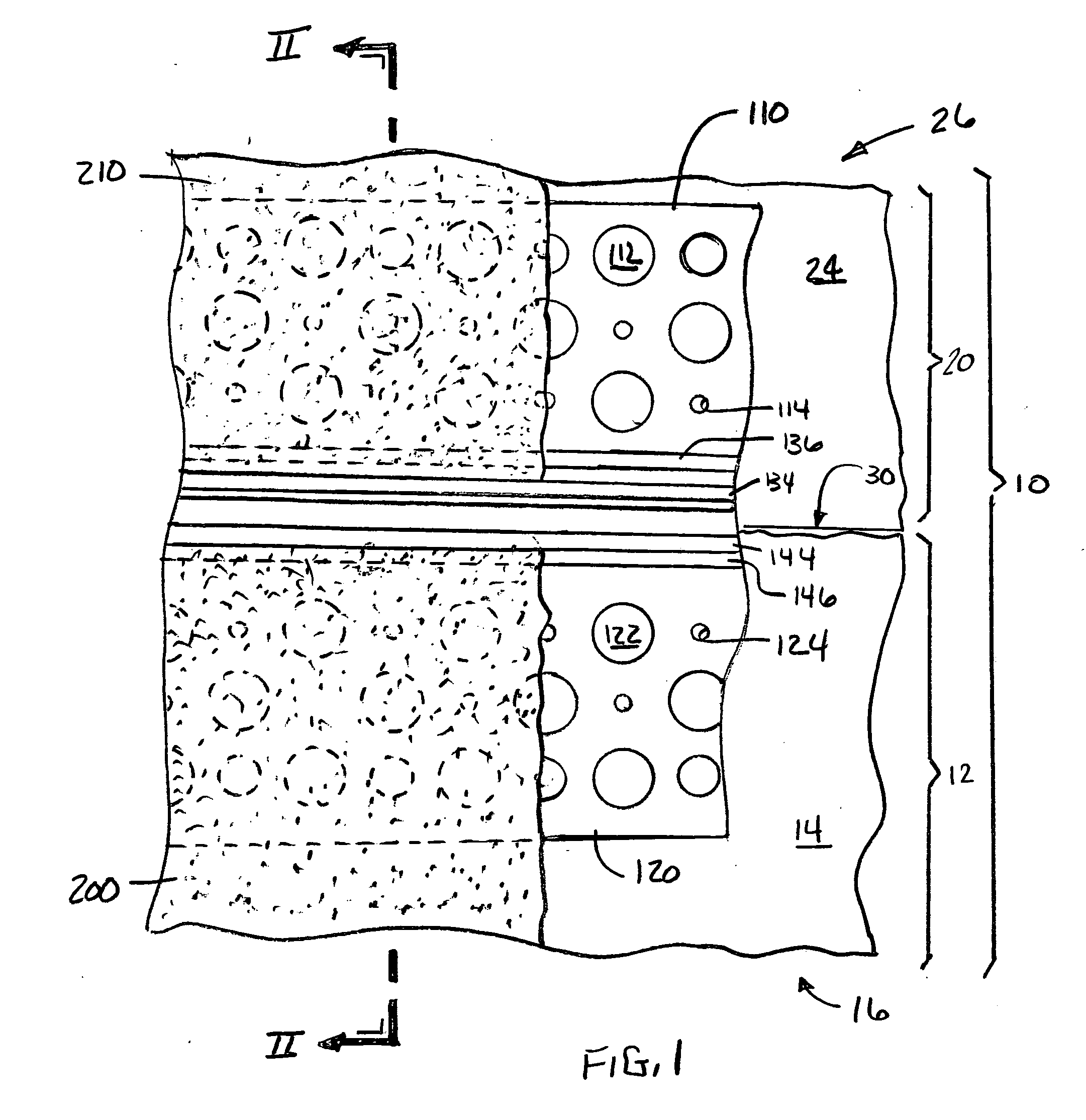
[0031] Referring now to the drawings for the purposes of illustrating the present embodiments of the invention only and not for the purposes of limiting the same, FIG. 1 illustrates one embodiment of the control joint 100 of the present invention used in connection with a multistory building 10. As will become further evident as the Detailed Description proceeds, various embodiments of the control joint of the present invention may be effectively used in connection with multistory structures that have walls constructed from dissimilar materials which would likely have differing expansion and contraction characteristics.

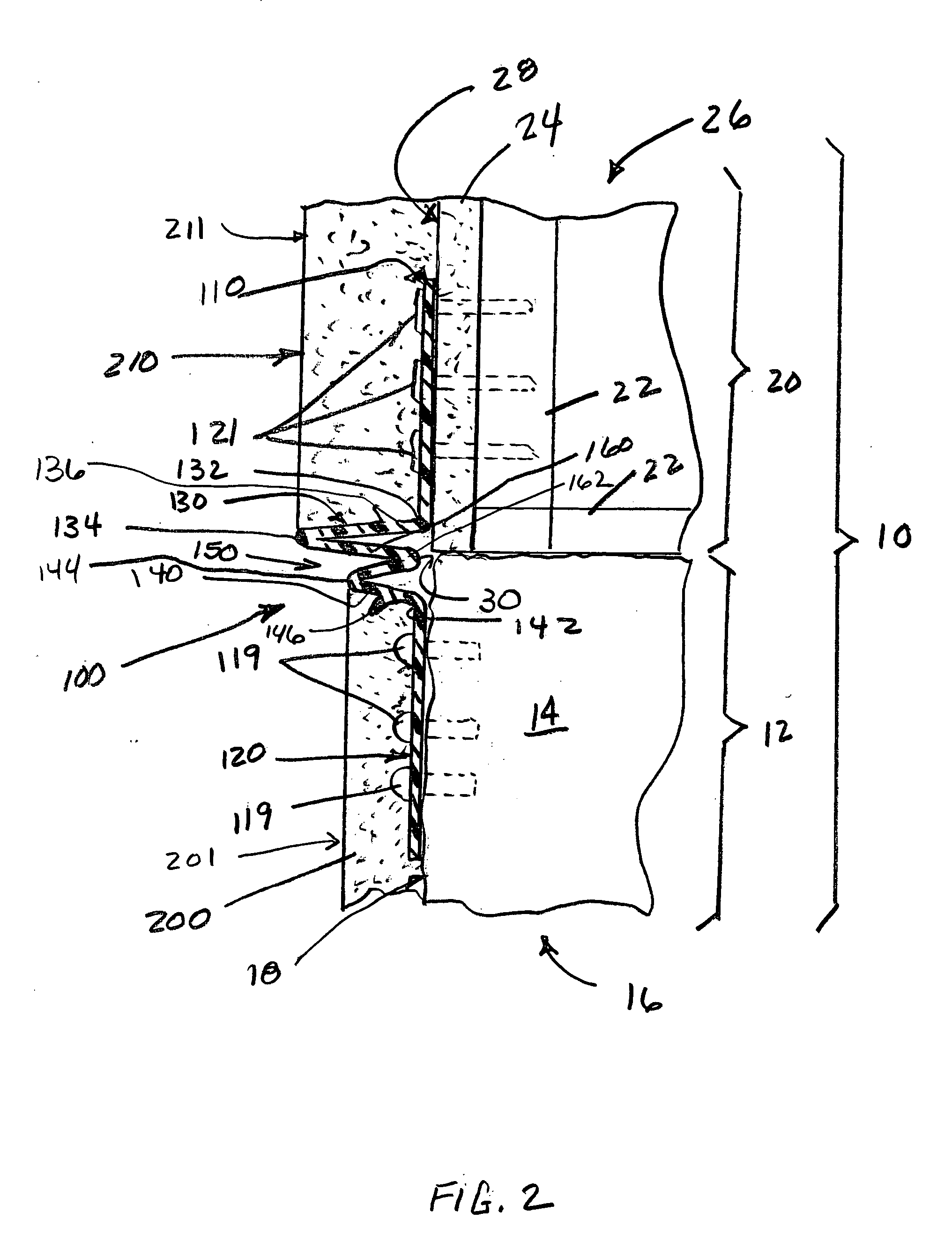
[0032] For example, as shown in FIG. 1, the first story 12 is fabricated from concrete block or solid concrete 14 to establish a first wall 16 that has a first exterior wall surface 18. The second or upper story 20 located on and attached to the first wall 16 may, for example, be constructed from wood or metal framing components 22. Wall board material 24 such as tha...


PUM


Abstract

A flexible control joint for use in plastering and stucco applications. Various embodiments of the flexible control joint may be used to form screed walls for different thicknesses of plaster materials applied to adjoining walls or other structures. The walls or other structures may be of similar or dissimilar constructions. Various embodiments of the control joint may be used to form corner arrangements or T-arrangements to achieve desired design effects.

Description

BACKGROUND OF THE INVENTION [0001] 1. Field of the Invention [0002] The invention relates to building construction components and, more particularly, to a flexible control joint for walls of dissimilar construction which facilitates the application of different thicknesses of plaster or similar material to the walls. [0003] 2. Description of the Invention Background [0004] Plaster, cement and stucco-type building materials have been employed in the construction of walls for residential and commercial buildings for many years to achieve a variety of different designs and wall textures. Various methods and application techniques exist for applying such materials to walls and other structures. One such method that is commonly employed involves attaching lath material to a wall frame constructed from wood or metal studs. The lath material serves to stabilize the plaster while it is in its flowable state prior to drying. Similar approaches are also commonly employed when the underlying s...

Claims


Application Information

Patent Timeline
IPC IPC(8): E04F15/22E04B1/62
CPCE04F13/06E04F2013/066
Inventor REYES, ERENIOKURPINSKI, MELVIN J.
Owner CLARKWESTERN DIETRICH BUILDING SYST
Why Eureka
Try Eureka