Inverter device and air conditioning system using inverter device

a technology of inverter device and inverter, which is applied in the direction of dc-ac conversion without reversal, electrical commutators, lighting and heating apparatus, etc., can solve the problems of simple structure only by shunt resistance and complex structure of current sensors, and achieves simple structure and high reliability , the effect of enhancing position detection

Active Publication Date: 2006-07-13
PANASONIC CORP
View PDF6 Cites 32 Cited by
  • Summary
  • Abstract
  • Description
  • Claims
  • Application Information

AI Technical Summary

Benefits of technology

[0048] In the three-phase modulation according to the invention, the current feeding in the carrier is configured to be added or subtracted in all three phases, and a situation of detecting only one phase is eliminated, and the position detection may be further enhanced.
[0049] The invention thus has an effect of realizing the inverter device and motor-integrated type compressor having a small size and high reliability.
[0050] Because the inverter device has a small size, light weight, and high vibration resistance reliability, when applied in a vehicle air conditioner having a motor-driven compressor, the invention assures a high reliability of a control device including the inverter device against the vibrations peculiar to a vehicle.

Problems solved by technology

As a result, the current sensors are complicated in structure, and a simple structure only by a shunt resistance can not be realized.

Method used


Image

  • Inverter device and air conditioning system using inverter device
  • Inverter device and air conditioning system using inverter device
  • Inverter device and air conditioning system using inverter device

Examples


embodiment 1

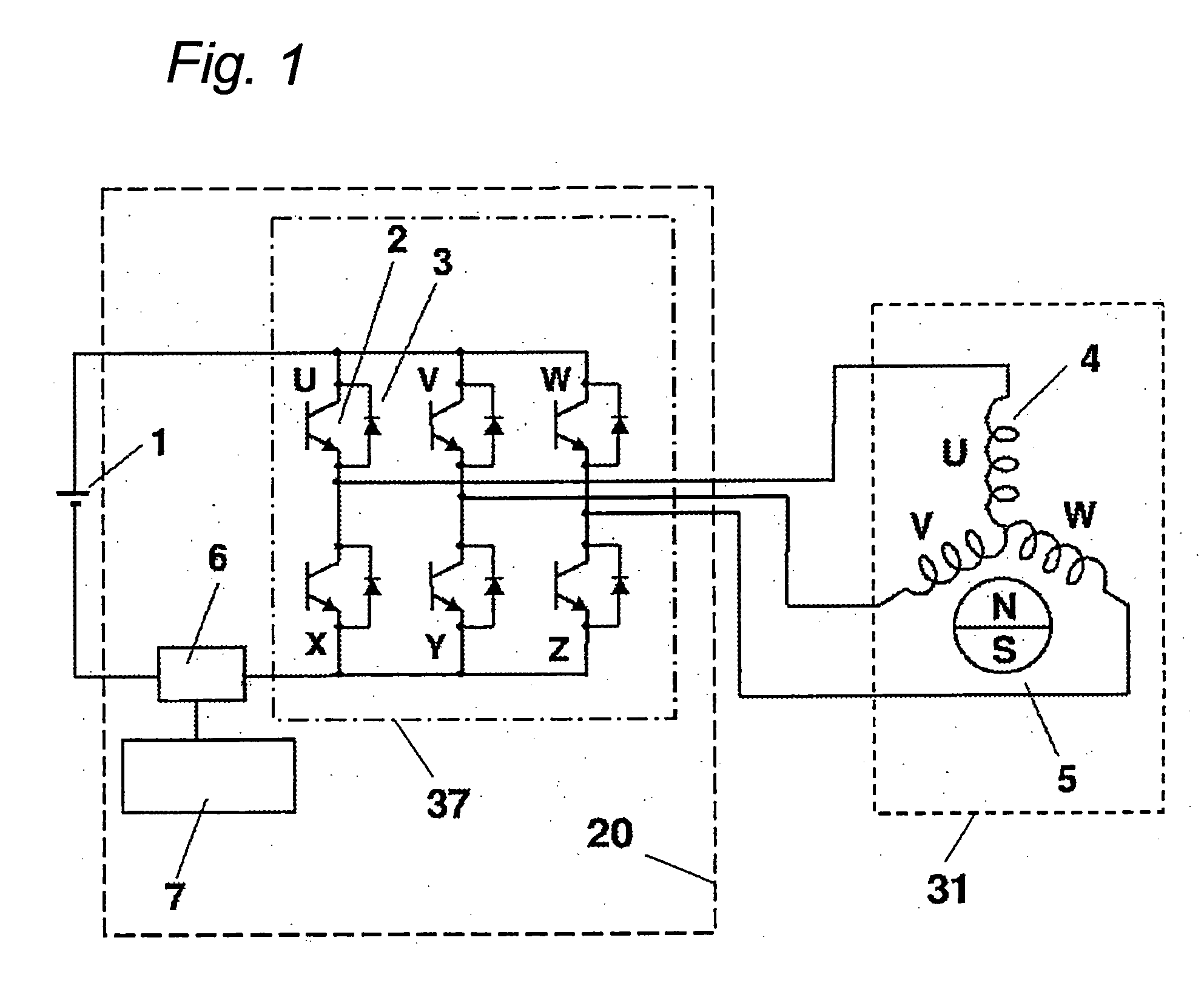
[0075]FIG. 1 is an electric circuit diagram of the present embodiment. In the diagram, reference numeral 1 is a battery, 2 is a switching element for an inverter operation connected to the battery 1, and 3 is a diode for an inverter operation. Reference numeral 4 is a stator winding of a motor, and 5 is a magnet rotor of the motor. Reference numeral 7 is a control circuit for controlling switching elements on the basis of a signal from a current sensor 6 acting as current detecting means. Reference numeral 37 is an inverter circuit, 20 is an inverter device, and 31 is the motor.

[0076] Here, comparing the electric circuit diagram in FIG. 1 with the electric circuit diagram for 120-degree current feeding driving in FIG. 22, it is not necessary to provide a comparator 128 and a phase shift circuit 127 in the embodiment 1.

[0077] Further, comparing the electric circuit diagram in FIG. 1 with the electric circuit diagram for sinusoidal driving having current sensors for phase current de...

embodiment 2

[0108] The embodiment 2 is explained with reference to FIG. 14 and FIG. 15. The embodiment 2 is intended to enhance the accuracy of detecting the position explained in FIG. 12 in the embodiment 1.

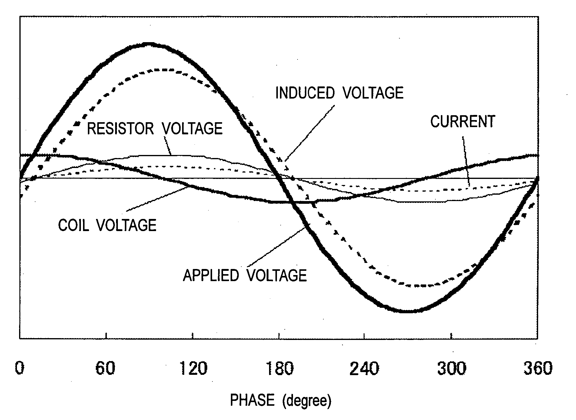
[0109]FIG. 14 shows the current feeding at the phase 30 degrees in FIG. 12, by shifting the U phase indicated by a thin solid line to the left side, and the W phase indicated by a thick solid line to the right side. As a result, not only the V phase, but also the current of U phase and current of W phase can be detected.

[0110]FIG. 15 shows the current feeding at the phase 30 degrees, by shifting the U phase to the left side, and the W phase to the right side in FIG. 13. As a result, the current of U phase and current of W phase can be detected. Also, in the current feeding at the phase 90 degrees, the V phase is shifted to the left side and the W phase is shifted to the right side.

[0111] As a result, both currents of V phase and W phase can be detected. At phases of 50 degrees and 70 deg...

embodiment 3

[0114] The embodiment 3 is explained with reference to FIG. 16. The present embodiment in FIG. 16 shows another method of enhancing the accuracy in detecting the position explained in FIG. 12 in the embodiment 1.

[0115] First, an effect of a three-phase modulation is described.

[0116] For reducing vibrations, it is preferred to use a three-phase modulation. In the three-phase modulation, the modulation range relative to the phase range is narrower compared to the case of the two-phase modulation, and a sinusoidal current is smoothed and a vibration becomes smaller.

[0117] In FIG. 8, in the case of the three-phase modulation, the ON period is added also to the V phase. As a result, in the center of the carrier period, all three phases of U, V, and W are turned on. When the three phases are turned on, no current flows in the current sensor 6, and it is the same when all three phases are turned off (power is not supplied to the motor from the power source in either case). Hence, the ca...


PUM


Abstract

A current sensor for detecting a power supply current is commonly used for detecting a current of a stator winding to detect a rotational position of a magnet rotor, so that a sinusoidal driving is realized without adding two current sensors for detection of a phase current, and also a phase shift circuit and a comparator needed in the conventional 120-degree current feeding are not required, and the number of components can be reduced. Therefore, an inverter device with a low noise and low vibration, having a small size, light weight and high reliability is obtained.

Description

BACKGROUND OF THE INVENTION [0001] 1. Field of the Invention [0002] The present invention relates to an inverter device for driving and controlling a sensorless DC brushless motor, and to an air conditioner applying such an inverter device to a motor-driven compressor using a sensorless DC brushless motor as a driving source. [0003] 2. Description of the Related Art [0004] The following explains an example of an air conditioner for a vehicle, which mounts a conventional motor-driven compressor using a sensorless DC brushless motor as a driving source, and which includes a battery or other DC power source. [0005]FIG. 20 shows a system configuration of an air conditioner for a vehicle. In the drawing, reference numeral 101 is an air duct, and air is sucked in through an air inlet port 103 by an action of an indoor fan 102, and after heat exchange by an indoor heat exchanger 104, the air is blown out into a vehicle compartment from an air blowout port 105. [0006] A refrigeration cycle ...

Claims


Application Information

Patent Timeline
Patent Type & Authority Applications(United States)
IPC IPC(8): H02M7/62F25B49/00H02M7/36H02P6/18H02M7/5387H02P6/06H02P6/08H02P6/182H02P6/28
CPCH02P6/18
Inventor GOTO, NAOMIMATSUI, KEIZOYOSHIDA, MAKOTO
Owner PANASONIC CORP
Why Eureka
Try Eureka